background image


13(33) 


2.  Structure Characteristics and Working Principle 

2.1  Main Functions 

SAL-UG series "Euro" Separate-vacuum hopper Loaders are suitable for 

conveying plastic granules over long distance. Utilizing high efficiency vacuum 

blower to produce vacuum in material hopper, plastic materials will then be fed 

into material hopper by outside pressure. 

2.1.1  Working Principle   


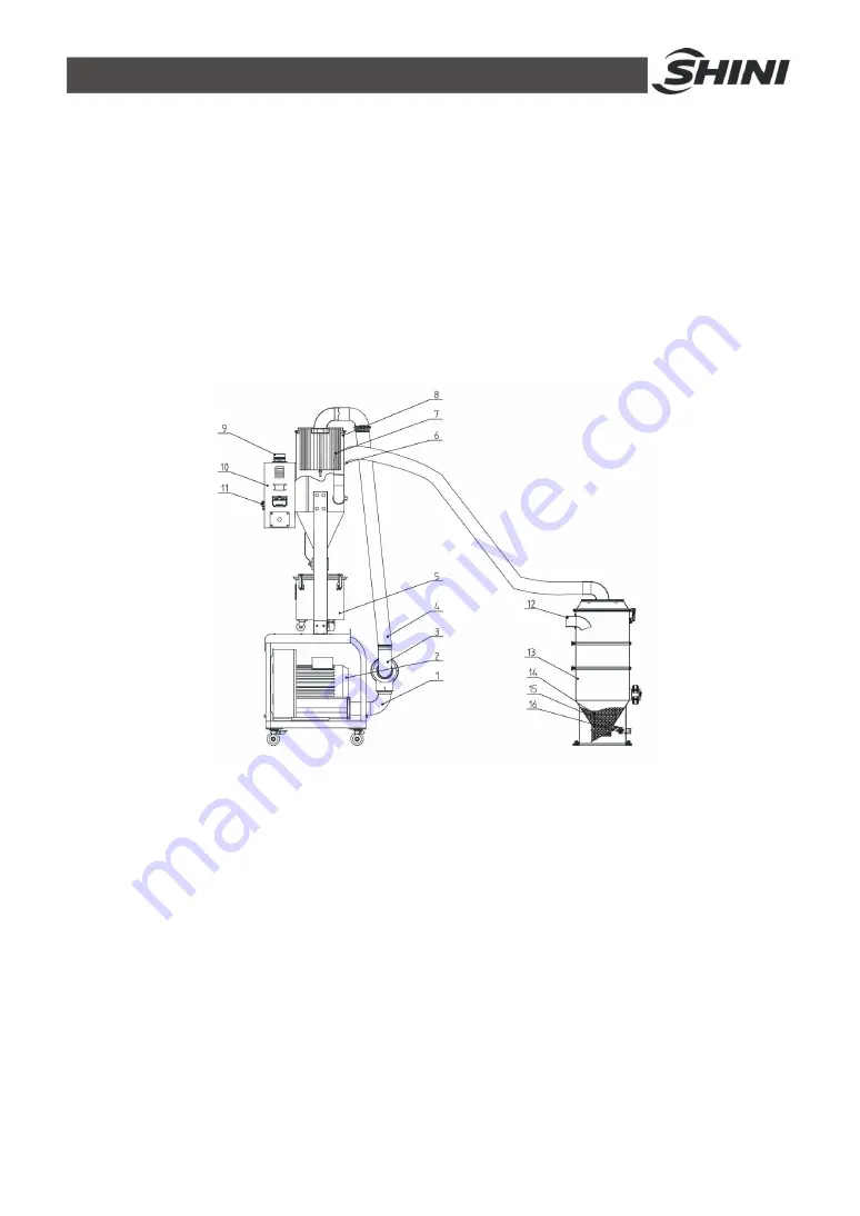
Names of Parts


1. Blower suction pipe   

2. Blower  

      3. Vacuum breaking diaphragm valve 

4. Steel wire hose  


5. Dust collecting barrel   

6. Air suction pipe 

7. Air filter 


8. Dust separating barrel 

      9. Alarm light   

10. Electric cabinet 


11. Main switch 


12. Material inlet 

13. Material hopper 

        14. Material   


          15. Discharging plate


16. Reed switch 

Picture 2-1: Working Principle 


After startup, when the reed switch (16) detected there

s no materials, the blower 

(2) starts working to generate negative-pressure vacuum inside the hopper (13). 

Meanwhile, the discharging plate (15) is closed, and materials (14) in the storage 

Summary of Contents for SAL-10HP-UG

Page 1: ...SAL UG Separate vacuum Hopper Loader Date Sep 2020 Version Ver C English ...

Page 2: ......

Page 3: ...1 Main Functions 13 2 1 1 Working Principle 13 3 Installation and Debugging 15 3 1 Install the Machine on the Dryer 15 3 1 1 Installation Elements 15 3 1 2 Installation Steps 15 3 1 3 Power Supply 16 4 Application and Operation 17 4 1 Control panel description 17 4 2 Parameter Setting 19 4 2 1 Parameter Setting 19 4 2 2 Communication Parameter Setting 22 4 3 Alarm Procedure 22 4 4 Operaton Procedu...

Page 4: ...le 33 6 7 1 About the Machine 33 6 7 2 Installation Inspection 33 6 7 3 Daily Checking 33 6 7 4 Weekly Checking 33 6 7 5 Monthly Checking 33 Form Index Table 1 1 Hopper Base Size 10 Chart 1 2 Specifications 10 Picture Index Picture 1 1 SAL UG Dimensions 9 Picture 1 2 Dimensions of Material Hopper 9 Picture 1 3 Loading Capacity 11 Picture 2 1 Working Principle 13 Picture 3 1 Installation Elements 1...

Page 5: ...5 33 ...

Page 6: ... SAL UG series separate vacuum hopper loader are based on the established design and now feature more attractive appearance better performance and improved ease of operation The whole range comprises of seven models equipped with vacuum blower from 1 to 15 HP Economy models can be offered on request Model SAL 5HP UG SHR 24U ...

Page 7: ...off box SBU directly Equipped with RS485 communication interface Equipped with audible and visual alarm SAL 5HP UG UGP D adopts integrated cyclone filter that can effectively reduce the filter loader SAL 10HP UG UGP D has auto cleaning function without shutdown that can prolong its working time The series of SAL UG UGP models are equipped with vacuum breaking valve to protect the protector SAL UG ...

Page 8: ...Any modifications of the machine must be approved by SHINI in order to avoid personal injury and damage to machine We shall not be liable for any damage caused by unauthorized change of the machine Our company provides excellent after sales service Should you have any problem during using the machine please contact the company or the local vendor Headquarter and Taipei factory Tel 886 2 2680 9119 ...

Page 9: ...9 33 1 3 Technical Specifications 1 3 1 Dimensions 5HP Main Unit 10HP Main Unit 20HP Main Unit Picture 1 1 SAL UG Dimensions 3U 6U 24U 36U 96U Picture 1 2 Dimensions of Material Hopper ...

Page 10: ...0 SAL 5HP UG D C 3 4 8 2 3Φ 1380 670 600 76 SVH 24U E 1 1120 360 375 13 1125 SAL 10HP UG C 7 5 8 6 3Φ 2015 620 795 160 SHR 36U 1 36 822 348 457 11 2 2 5 1600 SAL 10HP UG D C 2015 620 795 162 SAL 20HP UG D C 13 18 7 3Φ 2200 745 1000 236 SHR 48U 1 48 976 348 455 15 2 5 3 2000 Note 1 SVH L stands for photosensor hopper receiver We reserve the right to change specifications SHR E refers to vacuum hopp...

Page 11: ...abels All the electrical components should be installed by professional technicians Turn off the main switch and control switch during maintenance or repair Warning High voltage This sign is attached on the cover of control box Warning Be careful Be more careful at the place where this sign appears Attention No need for regular inspection because all the electrical parts in the control unit are fi...

Page 12: ... from liability for any costs fees claims and losses caused by reasons below 1 Any careless or man made installations operation and maintenances upon machines without referring to the Manual prior to machine using 2 Any incidents beyond human reasonable controls which include man made vicious or deliberate damages or abnormal power and machine faults caused by irresistible natural disasters includ...

Page 13: ...s of Parts 1 Blower suction pipe 2 Blower 3 Vacuum breaking diaphragm valve 4 Steel wire hose 5 Dust collecting barrel 6 Air suction pipe 7 Air filter 8 Dust separating barrel 9 Alarm light 10 Electric cabinet 11 Main switch 12 Material inlet 13 Material hopper 14 Material 15 Discharging plate 16 Reed switch Picture 2 1 Working Principle After startup when the reed switch 16 detected there s no ma...

Page 14: ...hree times the alarm light 9 on the control box 10 will light up to alarm During the blower s 2 suction process the air in the pipe enters the filter 7 through the recycler to remove the dust adhereded on the filter When the blower finishes the suction process the vacuum breaking valve 3 between the blower and the filter will produce the anti impact air flow to blow away the dust adhereded on the ...

Page 15: ...ion Elements Picture 3 1 Installation Elements 3 1 2 Installation Steps 1 Put the main body of the machine at a proper place and connect it with power supply 2 Install material hopper onto the dryer and connect it with signal wires from the main body 3 Use steel wire conveying hose to connect air suction pipe A on material hopper with air suction pipe D on main body Material suction B should be co...

Page 16: ...e power supply conforms to required specifications before installation SAL UG E Series should be connected with 3Φ 400V 50Hz Power supply or other specifications if required Note Make sure main switch is turned off before you connect the power ...

Page 17: ...17 33 4 Application and Operation 4 1 Control panel description Pic 4 1 Description of operation panel keys ...

Page 18: ...18 33 NO Graphical Interpretation 1 ON OFF 2 MENU 3 SET 4 DOWN 5 UP 6 FULL MAT LIGHT 7 BLENDING 8 MAT SHUT OFF 9 SHORTAGE ALARM 10 COMMUNICATION 11 FILTER MESH CLEAN ...

Page 19: ...de F 01 and press key to enter Press or key to change it to parameter 15 and press key to confirm after modification 4 2 1 Parameter Setting Code Status Parameters Preset value Range F 01 Suction action time Motor suction time when there s a shortage of materials which is also the vacuum breaking valve s working time Corresponding action D 15 secs 5 127 secs F 02 Shut off action time Start with th...

Page 20: ...o change the action time to 1 sec 1 1 4times F 05 Mixing action count cycle start setting Count from the first start up and start once mixing action after several times of repeated suction startings Set 1 as mixing materials every time Set F 03 to 0 without mixing once 1 9 times F 06 Setting time of cleaning before suction Set 0 as the no screen cleaning before suction Corresponding action R01 0 s...

Page 21: ...ortage that it should alarm 1 ENT key on the panel can be cancelled 2 Turn on off the power again Corresponding action A 04 3 F 10 99 F 12 The time waiting for motor stoppage suitable for sal 430 460 After motor starts it only takes next action after the time countdown is finished 20 secs 0 99 secs F 13 Buzzer alarm type 0 Lasting alarm 1 Slow and interrupted alarm 2 Fast and interrupted alarm 0 0...

Page 22: ...3 Shut down and check the pipe line When it sucks the materials again the alarm will dismiss or the ENT key on the panel can also be cancelled or turn on the power again A 03 Filter warning Filter screen blocking 1 Shut down and clean the filter screen Or replace filter screen The alarm will dismiss when turn on off the power again or it can be cancelled by clicking the ENT key on the panel A 04 S...

Page 23: ...127 secs Absoring masterbatch material Close the vacuum breaking valve after the action is stopped F 03 0 0 100 F 05 3 1 9 次 N01 Waiting time F 12 3 secs 0 99 secs R11 Cleaning filter screen The materials start to discharge to the hopper F 07 0 secs 0 99 secs R12 Waiting motor stop F 12 3 secs 0 99 secs N02 Waiting materials completely discharge to the hopper F 20 10 secs 5 99 secs N03 Waiting for...

Page 24: ...ate power Short circuit the two terminals of J2 Turn on the machine plate power Remove the short circuit of J2 s two terminals after three secs Completed Notes All parameter settings will be reset to factory settings Please use this function carefully ...

Page 25: ...t 8 bit 16 undefined 1 Real time info R 3 Suction action time R W 15 5 127 S 4 Screen cleaning action cycle R W 10 1 99 次 6 Screen cleaning setting time R W 0 99 S 7 Discharge checking time R W 10 5 99 S 8 Standby time after motor running R W 0 0 99 S 9 Screen cleaning setting time after suction R W 5 0 99 S 10 Waiting time for circulating suction R W 0 0 9990 10S 13 Input and output status R bit ...

Page 26: ...er screen 0 1 bit 5 wait for motor stop 0 1 bit 6 filter blocking alarm 0 1 bit 7 shortage alarm 0 1 bit8 bit15 undefined 15 Startup shutdown control W 0 startup 1 shutdown 16 Suction action time R W 15 5 127 S 17 Mixing proportion R W 0 0 100 18 Circulating startup setting of mixing action counting R W 1 1 9 times 19 Filter screen action cycle R W 3 1 99 times 20 Circulating suction waiting time ...

Page 27: ...0 0 0x03 set value times 36 Accumulating times of screen cleaning actions R 0 0 0x04 set value times 37 Accumulating times of material shortage alarm R 0 0 99 times 38 Startup shutdown control W 0 startup 1 shutdown 39 Current action R bit 0 startup 0 1 bit 1 standby 0 1 bit 2 cleaning the filter screen 0 1 bit 3 wait for motor stopping 0 1 bit 4 absorb the material 0 1 bit 5 absorb the masterbatc...

Page 28: ... 1 mat shortage stop alarm 0 1 bit 2 filter blocking alarm 0 1 bit 3 bit 15 undefined 45 The number of mixing layers R W 1 1 4 layer 46 Action mode only can be set in shutdown R W 5 1 5 Notes R means only reading W means only writing R W means writing and reading Note The password is not set in factory which can be set by users In case of loss please contact us ...

Page 29: ...r or machine sounds material shortage alarm 1 No materials left for conveying 1 Adding material 2 Air pipe breakage 2 Firmly lock it or replace 3 Cloth filter is blocked 3 Clean cloth filter Motor can not work Phase shortage or motor is burt out Check or replace Fuse melts each time you turn on the machine Short circuit or motor is burt out Check electrical circuit Motor overload alarm 1 Filter sc...

Page 30: ...ent personal injuries and damage of the machine 6 1 Material Hopper Clean material hopper periodically or when you find conveying capacity reduced Please loose the spring clips take down the hopper lid and take out filter screen Remove all the dusts and fines on filter screen and inside of material hopper ...

Page 31: ...ve the dusts adhering to the filter to keep good suction power 6 3 Glass Tube When you find that there are material grains clinging to the inner surface of glass tube please make it clean timely to keep proper function of the machine 1 Loosen the stainless steel pipe clamp and take down the installation flange 2 Blow the glass pipe with the air gun according to the direction of arrow to blow away ...

Page 32: ...n t work check the switch contact and replace with a new one if it doesn t work well 1 Check whether the wires are bad contacted 2 Please replace with a new one if the switch is damaged 6 5 Weekly Checking 1 Check if there are broken electrical wires or not Replace the broken wires immediately 2 Check the function of the keys on the control panel 3 Check if screws at material inlet and the seal ri...

Page 33: ...A Three phase A Check phase sequence of power supply 6 7 3 Daily Checking Check main power switch Check filter mesh Check working status of the motor 6 7 4 Weekly Checking Check all the electrical cables Check if there are loose connections of electrical components Check the screw of the feed in pipe s flange is loosed or not Check the air filter 6 7 5 Monthly Checking Check the spring lock on the...

Reviews: