


5
1
System
Components
■
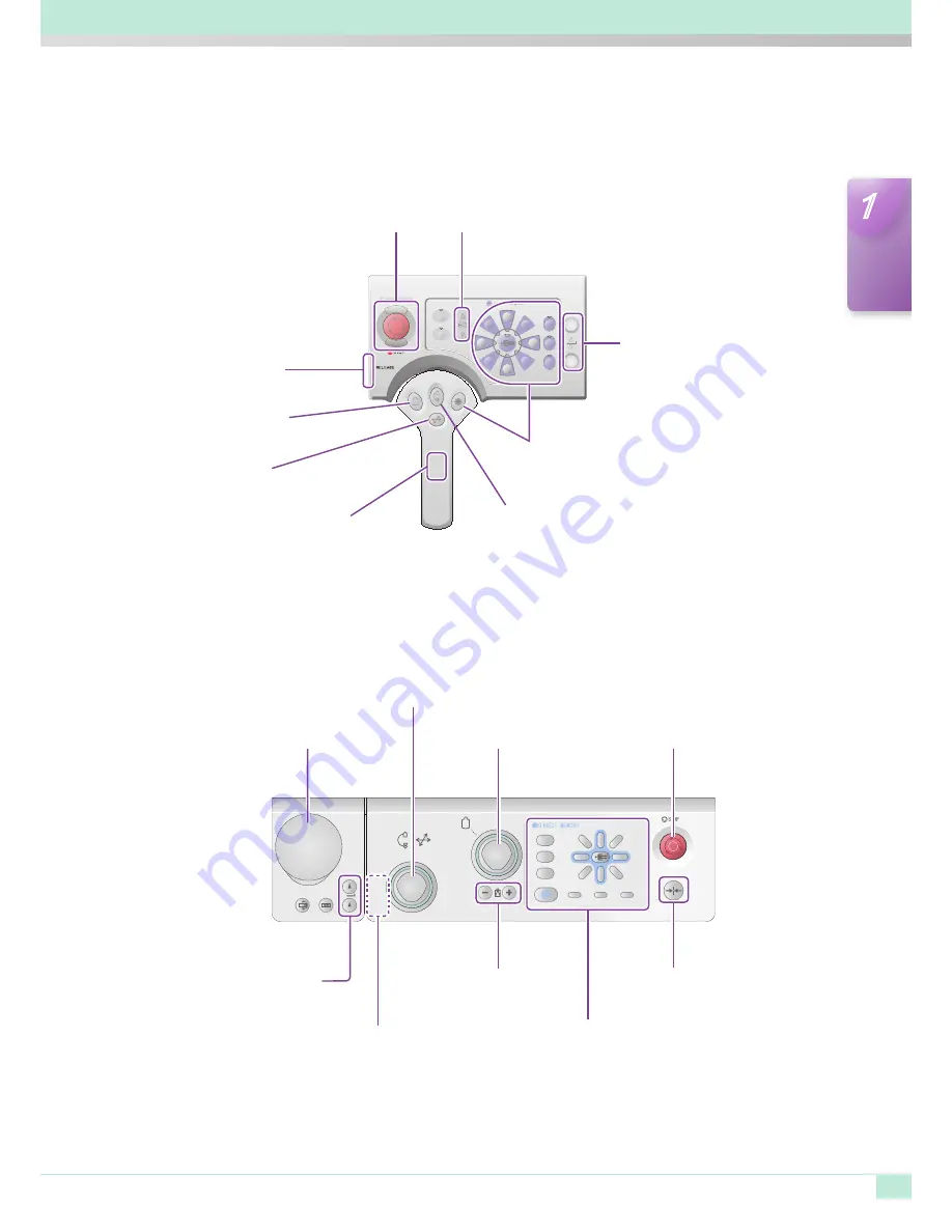
CyberGrip
Stop Switch
Release Switch
Field of View Switch
Catheterization Table
Up/Down Switch
Tabletop Unlocking Switch
(Located at the rear side of the grip)
C-arm Rotation Selector Switch
Direct Memory Switches
C-arm Travel
Selector Switch
FPD SID Switch
■
Cyber Console
Field of View
Switch
Center Reset
Switch
C-arm Rotation/Travel
FPD SID Confirmation Switch
Release Switch (on the side of the console)
Direct Memory Switches
Stop Switch
Catheterization Table
Up/Down Switch
Tabletop Unlocking Switch


