- 4 -
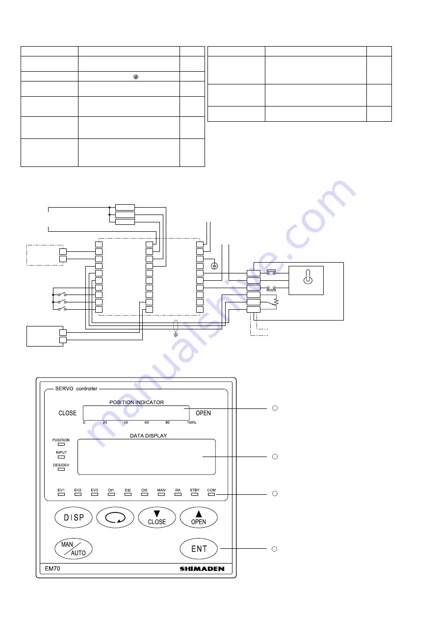
3-6. Terminal
Arrangement Table
Protective conductor
Protective grounding ( )
Power supply
100-240V AC
±
10% L
50/60Hz 13VA
N
11
12
13
Control input
Voltage/C
-
2
3
Analog output (option)
+
-
29
30
Control output
Contact as well as SSR M1 OPEN
M2
COM
M3
CLOSE
15
16
17
Feedback
potentiometer input
OPEN
R1
F.B.POT
R2
CLOSE
R3
4
5
6
Name of terminal
Description and Code
No.
Name of terminal
Description and Code
No.
External operation
input
COM
DI1
DI2
DI3
7
8
9
10
Event output (option)
Contact
COM
Contact
EV1
Contact
EV2
Contact
EV3
21
22
23
24
Communication
(option)
RS-232C: SG
RS-485: SG
SD
+
RD
-
26
27
28
3-7. Wiring Example
An example of wiring is shown. Particular attention should be paid to common lines and polarity.
INPUT DC
Power
supply
for motor
Power supply for EM70
100-240V AC~ 50/60Hz
L
N
CW
CW: Clockwise
CCW: Counterclockwise
Potentiometer
For example, (CMS: a product of Shinnihon Keisetsu)
(M904F: a product of Yamatake)
(For wiring for a motor, refer to the instruction manual of the motor manufacturer.)
Control motor
CCW
External operation circuit
Temperature
controller
Recorder
Analog
output
1
2
3
+
+
–
–
4
5
6
7
8
9
10
+
–
R1
R2
R3
COM
DI1
DI2
DI3
DI1
DI2
DI3
21
22
23
Event 3
Event 2
Event 1
24
EV-COM
EV1
EV2
EV3
25
26
27
28
29
30
+
–
11
12
13
14
Grounding
M1
M2
M3
15
16
17
18
19
20
2 (S)
3 (C)
1 (0)
Y (W)
T (R)
G (B)
Event
Power supply
Contact rating: 1A 240V AC ~
4. Names and Functions of Parts on Front Panel
Position indicator
Data display
Action display lamps
Operating keys
1
2
3
4


