


8
SETUP
Connect Hose and Gun
Remove the plastic cap from the outlet tee, and connect
a 50 ft. (15 m) (minimum length) fluid hose to it. Connect
the other end of the hose to the spray gun. Don’t use
thread sealant, and don’t install the spray tip yet!
To avoid damaging the pressure control, which
may result in poor equipment performance and
component damage, follow these precautions:
1.
Always use a minimum of 50 ft. (15.2 m) nylon
spray hose.
2.
Never use a wire braid hose as it is too rigid to
act as a pulsation dampener.
3.
Never install any shutoff device between the
outlet of the pressure control and the main
hose.
4.
Never allow flushing water or water base paint
to freeze in the system.
CAUTION
Fill Packing Nut/Wet Cup
Fill the packing nut/wet cup 1/3 full with throat seal liquid,
supplied. Keep the wet cup filled to help protect and pro-
long the life of the pump’s throat packings.
Check Electrical Service and Plug In
Be sure the electrical service is 120 VAC, 60 Hz, 15 Amp
(minimum) and that the outlet you use is properly
grounded.
Use a grounded extension cord which has 3 wires of a
minimum 12 gauge size, and a maximum of 200 ft. (61
m) long. Longer lengths may affect sprayer performance.
Do not remove the grounding prong of the power supply
cord plug, and do not use an adapter.
Be sure the ON/OFF switch is OFF.
Plug the power supply cord into a grounded electrical out-
let that is at least 20 ft. (6 m) away from the spray area
to reduce the chance of a spark igniting the spray vapors.
Set Pressure Control
Turn the pressure control knob to the lowest setting.
Flush the Pump
An important part of the care and maintenance of your
sprayer is proper flushing. Refer to page 9.
CAUTION
Never operate the sprayer without the drain valve
in place. The drain valve is used to help relieve sys-
tem pressure and to help prime the sprayer.
Do not attach a spray hose to the drain valve; doing
so could result in costly damage to the pressure
control.
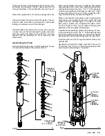
PRESSURE CONTROL
KNOB
1/4 NPT(M)
OUTLET
DRAIN VALVE
PACKING NUT/
WET CUP
FILL HERE
0804
Prepare the Paint
Prepare the paint as instructed by the manufacturer. Re-
move any skin that may have formed. Stir the paint to dis-
solve pigments. Strain the paint through a fine, nylon–
mesh bag (available at most paint dealers) to remove
particles that might clog the spray tip.
This is probably the
most important step toward trouble–free spray painting.
New paint seldom needs thinning. Add solvent to old and
remixed paints to replace the solvent lost through evapo-
ration. Do not add too much solvent as thin paint is hard
to control and doesn’t cover very well. Follow the paint
manufacturer’s recommendations on thinning.
Prime the Sprayer
Close the drain valve. Don’t install the spray tip yet! Put
the suction tube into the paint container. Turn the pres-
sure adjusting knob all the way counterclockwise to lower
the pressure setting. Disengage the gun safety latch.
Hold a metal part of the gun firmly against and aimed into
a grounded metal waste container. Squeeze the trigger
and hold it open, turn the ON/OFF switch to ON, and
slowly increase the pressure setting until the sprayer
starts. Keep the gun triggered until all air is forced out of
the system and the paint flows freely from the gun. Re-
lease the trigger and engage the safety.
NOTE: If the pump is hard to prime, place a container
under the drain valve and open it. Let the sprayer
run until paint is running through the drain valve.
Close the drain valve. This method bleeds the air
from the pump. Then release the gun safety
latch and trigger the gun to prime the hose as in-
structed previously, under Prime the Sprayer.
Check all fluid connections for leaks. If any are found, fol-
low the Pressure Relief Procedure, page 2, before
tightening connections.


