


16
820-008
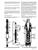
CONNECTING ROD AND BEARING
WARNING
To reduce the risk of serious bodily injury, including
fluid injection; splashing in the eyes or on the skin;
injury from moving parts or electric shock, always
follow the Pressure Relief Procedure Warning
on page 12 before continuing.
Remove the pump as described on page 14. Remove the
four screws (58) and the cover (59). Remove the two
capscrews (61) and lockwashers (9). Remove the bear-
ing (63) and the connecting rod (64), sliding the connect-
ing rod off the crankshaft. (J). See Fig 5.
Use a screwdriver to push the retaining spring (55) aside
and remove the pin (57) from the coupling (56). Remove
the coupling from the connecting rod (64).
Pull the connecting rod (64) out of the bearing (63). Wipe
it clean (don’t use solvent) and inspect the surfaces of the
bearing and the connecting rod link (K) for wear or dam-
age. If either needs replacing, replace both of them.
When installing the rod and the bearing, coat the sur-
faces with SAE 10 non–detergent motor oil.
Clean and inspect the crankshaft. (J). Wipe it clean with
a rag; do not use solvent. If the crankshaft. is badly worn,
replace the drive assembly.
Clean and inspect the connecting rod needle bearing (L).
Repack bearing with industrial, heavy–duty, extreme–
pressure, lithium–soap grease.
NOTE: After every 100 hours of operation, or whenever
servicing the pump (whichever comes first), fill
the cavity in connecting rod (64) with SAE 10
non–detergent motor oil.
Fig 5
64
63
55
56
57
9
61
59
58
J
K
L
LUBRICATE – SEE NOTE IN TEXT
0745
Assemble new rod and bearing, being sure to push the
spring (55) down in place over the pin (57) ends, and in-
stall it in reverse order of removal.
DRIVE ASSEMBLY
WARNING
To reduce the risk of serious bodily in-
jury, including fluid injection; splash-
ing in the eyes or on the skin; injury
from moving parts or electric shock,
always follow the Pressure Relief
Procedure Warning on page 12 be-
fore continuing.
Fig 6
25
24
70
69
68
24
67
66
A
B


