


14
DISPLACEMENT PUMP
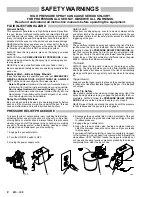
WARNING
To reduce the risk of serious bodily injury, including
fluid injection; splashing in the eyes or on the skin;
injury from moving parts or electric shock, always
follow the Pressure Relief Procedure Warning
on page 12 before continuing.
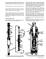
Removing the Pump
Flush the sprayer if possible.
Remove the hose clamps (87, 88) and move the drain
tube (90) away from the pump. Unscrew and remove the
suction tube (52). Remove the adapter (50). See Fig 1.
Disconnect the hose (20) from the nipple (22). See Fig 1.
Push the retaining spring (55) up. Push out the pin (57).
Loosen the cylinder locknut (103) and unscrew the pump
(26) from the drive assembly (65).
See Disassembling the Pump, below.
Installing the Pump
To reinstall the pump, rotate the crankshaft so that the
connecting rod (64) is in its lowest position. Pull the pump
piston rod (47) about 1–1/2 inches out of the cylinder
(46), and turn the rod so the pin hole is about 90
_
from
the outlet nipple (22). Screw the cylinder locknut (103) all
the way down.
Screw the pump (26) into the drive assembly (65) until the
holes in the piston rod and the connecting rod are
aligned. Insert the pin (57) and push the retaining spring
(55) down over the pin.
Screw the pump cylinder
completely into the drive as-
sembly; you will feel some resistance from the packings.
Now turn the cylinder back until the outlet nipple (22)
faces back. Screw the hose (20) onto the nipple; tighten
it securely. To avoid having the cylinder locknut (103)
loosen due to vibration, tighten the locknut up against the
drive housing to 70 ft–lb (95 N.m).
Reassemble remaining parts reverse from disassembly.
NOTE: Use Repair Kit No. 820–549 to repair the pump.
See page 23. Use all the parts in the kit, even if
the old ones look good. Old and new parts do not
seal together well, and the pump may leak.
Disassembling the Pump
Remove the pump from the sprayer as described above.
Unscrew the intake valve (48) from the cylinder (46). If
the valve is seized in the housing, squirt penetrating oil
around the threads and gently tap around the housing
with a light hammer to loosen. See Fig 2 and 4. Remove
the ball guide (40), the stop pin (39) and the ball (28).
Clean and inspect the parts for wear or damage.
NOTE: Test the intake valve by filling it with solvent and
seeing if any solvent leaks past the ball. It
shouldn’t leak. The valve must be clean for this
test; any dirt will hold the ball off the seat and let
the solvent leak past.
Fig 1
Fig 2
88
87
90
65
55
64
57
20
22
26
52
46
28
40
41
48
39
47
50
103
0742
TORQUE TO
70 ft–lb
(95 N.m)


