Sherman DIGIMIG 225GDS User Manual Download Page 18


18 

Changing the value of inductance also affects the reduction of spatter during arc welding CO

 2.

 The inductance value is greater than (+) reducing the 

Changing the value of inductance also affects the reduction of spatter during arc welding CO

 2.

 The inductance value is greater than (+) reducing the 

Changing the value of inductance also affects the reduction of spatter during arc welding CO

 2.

 The inductance value is greater than (+) reducing the 

amount of spatters when the value is negative (-), increases the amount of spatter. Optimal setting inductance value depends on several factors and may 
deviate from the standard recommendations and therefore should be chosen experimentally during the welding tests.

Adjustment of this parameter also allows for brazing thin (3 mm) of the galvanized wires made of copper alloy CuSi3 shielded pure argon or, in certain 
cases mixtures of Ar / CO

 2

 the ratio (82/18).

cases mixtures of Ar / CO

 2

 the ratio (82/18).

cases mixtures of Ar / CO

 2

 the ratio (82/18).

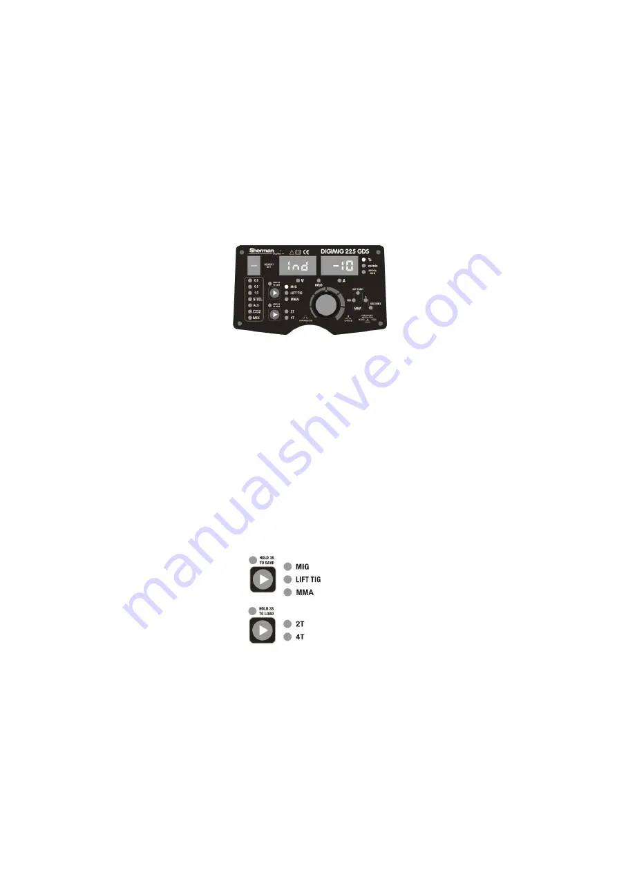
To adjust the inductance must press the knob (F) until the left display shows "Ind." Turn the knob to change the inductance of the recommended range:

- 10% (hard arc / weld convex / greater spatter) / + 10% (soft arc / weld flat / less spatter). 

7.3.1.1 Saving and loading memory settings for programs in synergy mode 

In synergic welding mode DIGIMIG 225GDS can save 10 independent programs containing MIG welding parameters and functions of the device 
settings. Recording mode and charging is described in point. 6 B and E.

7.3.2 Manual mode 

The device has the ability to switch at any time of the operation mode of action version of the synergistic manual mode. It is advisable to preset welding 
conditions described in section 7.3.1, which allows for selection of an optimal voltage and wire feed speed for typical welding parameters. If the weld 
quality is not adequate voltage must be adjusted constantly working in synergy mode. If the results are not satisfactory to be referred to as change from 
synergies to manual control device, which allows independent adjustment of three welding parameters: welding voltage, wire feed speed, and the 
inductance

arc. To switch to manual mode must be simultaneously pressed for

3 seconds both buttons memory 

The device switches to manual mode will be disabled, LEDs panel (C), which is a signal that the apparatus came mode synergistic, and the last 
parameter setting welding mode synergistic (voltage, wire feed speed and inductance) is a set of active possible for independently controlling . You can 
then sequentially pressing the knob (F) to select each of the three welding parameters and the adjustment made in accordance with the expectations of 
the operator.

7.3.2.1 Saving and loading memory settings for programs in manual mode 

The unit working in manual mode is ready to save welding parameters in a separate package of 10 sets of manual (0-9). To save and load these sets 
follow the same way as in section 6 B and E. But keep in mind that the saved parameters manually shaped and synergistic

Summary of Contents for DIGIMIG 225GDS

Page 1: ...V1 2 03 18 21 USER MANUAL WELDING RECTIFIER synergistic Inverter DIGIMIG 225GDS...

Page 2: ...g refer to the applicable health and safety regulations in the workplace During electric arc welding MIG MAG there are the following risks ELECTRIC SHOCK ARC NEGATIVE IMPACT ON HUMAN EYES AND SKIN PAI...

Page 3: ...the charger in a place that allows its easy handling Persons operating welder should have the power to electric welding MIG MAG know and comply with applicable health and safety regulations when perf...

Page 4: ...experience and hobbyists The device is IGBT allowing a considerable reduction in the weight and dimensions of the welding device and an increase in efficiency while reducing power consumption Welding...

Page 5: ...in the welding current which results in stabilizing the arc Reducing the value of the function gives a soft arc and a smaller depth of penetration while increasing the value of the function causes dee...

Page 6: ...Cord 7 The gas connection 8 The power switch 5 1 Wiring 5 1 1 Method MMA Welding the wire ends to terminals 2 and 5 located on the front panel so that the electrode holder was appropriate for the ele...

Page 7: ...carrying capacity of 200A equipped with a shielding gas control valve Current terminal holder should be connected to the negative pole 2 and the gas conduit to the regulator to the gas cylinder The po...

Page 8: ...connected to MIG 1 Gas conduit from the regulator lead and attach to the gas nozzle 7 on the rear wall of the housing Plug polarization changes 3 in the socket 5 The negative pole of a source 2 connec...

Page 9: ...t holder should be connected to MIG 1 Plug polarization changes 3 in the socket 5 The negative pole of a source 2 connected to the work piece by means of a wire with a clamp Plug the device into a pow...

Page 10: ...he current to power equipment and pull wire holder welder using speed wire feeding 10 When you see the wire in the outlet handle release button and screw the current 11 Adjust the pressure force by th...

Page 11: ...choice of the appropriate method is confirmed by lighting of the LED Pressing the button for 3 seconds to go to the store mode settings The choice of method of welding Short press the button to switch...

Page 12: ...voltage type of material the wire diameter the MIG mode synergy voltage and wire feed speed the value of inductance introduced by the correction voltage type of material the wire diameter the kind of...

Page 13: ...tion charging mode settings saved The display shows the number of the program to be loaded Knob F you can change the program number Pressing the button will load the selected program and switching off...

Page 14: ...on To enable or disable the VRD should set the welding current 108 A then press the key for 3 seconds 2T 4T E VRD cases may hinder the arc ignition To enable or disable the VRD should set the welding...

Page 15: ...lect the welding voltage wire feed speed and inductance as required DIGIMIG 225GDS welder is an automatic function 3 second delay after the end of the gas discharge welding process allowing to solidif...

Page 16: ...of material being welded the diameter of the wire used and the nature of the protective gas The choice of material In order to select the type of material to be welded in sequence to press the knob F...

Page 17: ...gs material species wire diameter and shielding gas should proceed to the welding process parameters compatible with the proper synergistic program Wire feed speed and welding voltage corresponding kn...

Page 18: ...of the device settings Recording mode and charging is described in point 6 B and E 7 3 2 Manual mode The device has the ability to switch at any time of the operation mode of action version of the sy...

Page 19: ...of two programs for aluminum welding The programs were selected for welding wire ALSi5 type ER 4043 primarily intended for aluminum casting and wire AlMg5 type ER 5356 which is suitable for welding a...

Page 20: ...ure argon high quality class preferred not less than 4 8 The gas flow should be selected according to the thickness and travel speed Good welding results are achieved when the process occurs in the di...

Page 21: ...20 21 20 21 45 50 45 50 45 50 10 15 10 15 10 15 10 15 10 15 10 15 4 5 1 0 1 2 1 0 1 5 1 0 1 5 1 0 1 5 160 180 160 180 160 180 22 23 22 23 22 23 45 50 45 50 45 50 15 15 1 2 1 2 1 6 1 2 1 6 1 2 1 6 220...

Page 22: ...3 0 8 0 9 47 0 47 0 100 130 20 21 100 130 20 21 100 130 20 21 100 130 20 21 100 130 20 21 45 50 45 50 45 50 10 10 15 10 15 10 15 1 0 1 2 47 0 47 0 120 150 20 21 120 150 20 21 120 150 20 21 120 150 20...

Page 23: ...rrupt the power supply since the continuously operating fan cools the heat sinks inside the unit to more quickly reduce the temperature After restarting be sure to limit the welding parameters for fur...

Page 24: ...device by purging with compressed air to remove dust and chips from metallic plates and the control wires and electrical connections Not less than once every six months should be a general review of t...

Page 25: ...ed to the complaint must be packed in the original carton and protected by Styrofoam original fittings TECWELD company is not liable for damage caused by a welder during transport If you wish to disca...

Page 26: ...Q 3 4 1 2 3 C ABOUT N 2 temperature check Fan count 1 P C N 1 1 P C N 2 T 3 C 7 0 C 6 9 C 2 C 4 D B 1 t R R 1 1 P C N 4 R 1 1 7 R 1 1 9 24V R 1 2 9 R 1 1 2 R 1 2 3 1 Q 2 8 1 R 1 1 4 R 1 1 5 R 1 1 6 R...

Page 27: ...II RoHS Directive 2011 65 EU and is compliant with the following standards BS EN 60974 1 2013 04 Arc welding equipment Part 1 Welding power sources BS EN 60974 1 2013 04 Arc welding equipment Part 1 W...

Reviews: