


32
ST SERIES
REASSEMBLING THE ENGINE
❱❘
Crankcases assembly
•
Make sure that the centering rings are in place on
the right crankcase and that the washers of the
gearbox shafts are also in place.
•
Grease the oil seals of the left crankcase and put it
in place.
•
Put the screws and tighten to
10 Nm
.
•
Then tap lightly with a plastic mallet on the
crankshaft and check that the shafts turn without
any hard point.
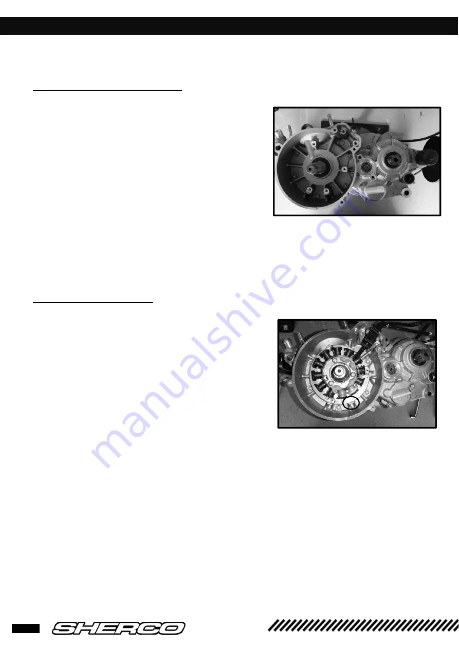
❱❘
Ignition assembly
•
Mount the stator on the crankcase and make sure
that the marks are aligned. Tighten the 3 M6 screws
to
10 Nm.
•
Position the hall sensor and tighten the two screws
to
8 Nm
.
Summary of Contents for ST 125
Page 1: ...ST SERIES...
Page 2: ...1...
Page 46: ...44 ST SERIES CABLE SCHEMATICS Homologated light harness...
Page 47: ...45 ST SERIES CABLE SCHEMATICS Homologated light harness...
Page 48: ...46 ST SERIES CABLE SCHEMATICS Racing light harness...
Page 49: ...47 ST SERIES CABLE SCHEMATICS Principal harness...
Page 50: ...48 ST SERIES CABLE SCHEMATICS Principal harness...
Page 51: ......


