XE-A212V
DIAGNOSTIC PROGRAM
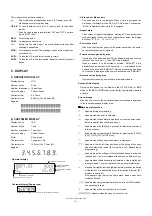
– 13 –
3) PRINTER TEST
1
Key operation
102
3
2
Test procedure
At the receipt setting, the logo is also printed and the receipt is
issued.
3
Check:
The print is free from contamination, blur, and uneven density.
4
End of testing
The test will end automatically.
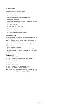
4) KEYBOARD TEST
1
Key operation
_ _ _ _104
3
2
KEY check sum code
2
Test procedure
The keyboard is checked using the sum check code of the key code.
If the sum check code is not entered, the check is made using the
sum check code of the default keyboard arrangement.
The sum check data for each model is entered to the front 4 digits of
the DIAG code, and that data is compared with the key data added
until the final key (CA/AT) is pressed.
Both data are the same, the test ends, printing the number given
below.
If both data are different, the printer prints the error message.
3
Check:
A) The content of completion print
4
End of testing
Note: Calculation of key sum check data
Hard codes (hexadecimal number) at the position (excluding
feed key) where there is an input data contact are added.
However, the end key (CA/AT) is not added.
This data to which hard codes have been added is converted into
a decimal number value, which will become the sum check data
that will be entered when DIAG is started.
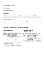
5) MODE SWITCH TEST
1
Key operation
105
3
2
Test procedure
The above X must be read in the correct order. (If the contact is
open, 9 will be displayed.)
3
Check:
The display during testing and the content of the completion print.
4
End of testing
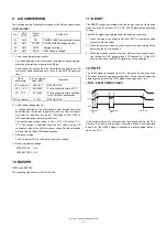
6) PRINTER SENSOR TEST
1
Key operation
106
3
2
Test procedure
Check the status of the paper end sensor and head up sensor.
3
Check the following.
4
End of testing
You can exit the test mode by pressing any key and the printer prints
the following.
1 0 6
7) CLOCK TEST
1
Key operation
107
3
2
Test procedure
3
Check:
“–“ blinks and the clock counts up.
4
End of testing
When any key is pressed, the date and time are printed and the test
mode will be terminated.
When the test ends normally:
1 0 4
When an error occurs:
(xxxx is the value which added the key code.)
E – – xxxx
1 0 4
PO
P R I N T E R
P G M
OP display
3 lines of 24 digits are printed.
Z Z Z Z Z Z Z Z Z Z Z Z Z Z Z Z Z Z Z Z Z Z Z Z
Z Z Z Z Z Z Z Z Z Z Z Z Z Z Z Z Z Z Z Z Z Z Z Z
Z Z Z Z Z Z Z Z Z Z Z Z Z Z Z Z Z Z Z Z Z Z Z Z
PO
K E Y
B O A R D
P G M
OP display
KEY CODE
1 0 4
When the test ends normally
1 0 5
When an error occurs:
E – ~ –
1 0 5
X: 1 - Paper present
O - No paper
Y: 1 - Thermal head down
O - Thermal head up
PO
M O D E
1 0 5
S W
X
P G M
OP display
MODE: PGM_ _ _OP X/Z_REG_MGR_X1/Z1_X2/Z2__
X :
1
2
OFF
3
4
5
6
7
PO
H / P
S E N S O R
P G M
X
Y
OP display
1 0 6
PO
T I M
C H E C K
P G M
OP display
Hour
Blinks at an interval of 0.5 sec.
Min.
Sec.
E R
107
Y Y M M D D
h h m m s s
year
month
day
hour
min.
sec.
Summary of Contents for XE-A212
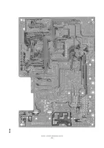
Page 24: ...XE A212V CIRCUIT DIAGRAM AND PWB LAYOUT 23 PWB LAYOUT MAIN PWB LAYOUT A side ...
Page 25: ...XE A212V CIRCUIT DIAGRAM AND PWB LAYOUT 24 B side ...
Page 26: ...MEMO ...
Page 27: ......


