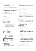
XE-A212V
DIAGNOSTIC PROGRAM
– 15 –
11) FLASH ROM TEST
1
Key operation
130
3
2
Test procedure
The test program checks that the checksum of the flash ROM
(Bank0: F80000H ~ FFFFFH).
The lower two digits of the checksum should be 10H. (pending)
3
Check:
The completion print.
4
End of testing
The test will automatically be terminated and the printer prints as fol-
lows:
12) AD CONVERSION PORT TEST
1
Key operation
160
3
2
Test procedure
The test program displays the voltage of each AD conversion port.
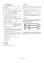
13) RS232C TEST
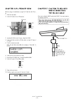
Install the RS232C loopback connector.
1
Key operation
500
3
2
Test procedure
The test program checks the control signals.
Data communication check
A loopback test of 256-byte data is performed between SD and RD.
DATA: $00 - $FF BAUD RATE: 9600 BPS
3
Check:
The completion print.
4
End of testing
3. KEY CODE TABLE
When the test ends normally:
1 3 0
ROM
********
(Model name)
********
(Version)
When the test ends
abnormally:
E – – ~ – –
1 3 0
ROM
********
(Model name)
********
(Version)
PO
R O M
F L A S H
P G M
OP display
1 3 0
PO
T M
P G M
OP display
Display
1 6 0
=
V R F
P G M
OP display
1 6 0
=
V P T E S T
P G M
OP display
1 6 0
=
End of testing
OUTPUT
INPUT
/ER
/RS
/DR
/CI
/CD
/CS
OFF
OFF
OFF
OFF
OFF
OFF
OFF
ON
OFF
OFF
ON
ON
ON
OFF
ON
ON
OFF
OFF
ON
ON
ON
ON
ON
ON
Completion print
RS TEST
OK
500
Error print
RS TEST
**NG**ERxx
500
xx Contents of error
01 ER DR error
02 ER CI error
03 RS CD error
04 RS CS error
05 SD RD error
DATA error
06 SD RD error
DATA error/framing error
PO
R S
T E S T
P G M
OP display
5 0 0
2 3 2 C
098
112
119
087
071
151
007
032
096
135
082
146
034
023
048
103
130
066
050
017
018
055
113
129
081
145
001
002
039
097
131
083
147
019
003
033
115
116
068
148
052
020
049
051
132
086
054
036
004
065
084
118
150
038
022
006
035
100
134
070
053
021
005
067
102
085
069
149
037
024
099
101
104
072
152
040
008
133
117
136
088
056
025
009
120
089
073
153
057
041
010
121
105
122
154
058
042
026
138
106
090
074
075
059
043
155
107
123
139
091
027
011
128
064
080
144
016
000
CHECK SUM :
XE-A212V
9029
Summary of Contents for XE-A212
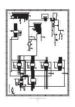
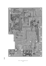
Page 24: ...XE A212V CIRCUIT DIAGRAM AND PWB LAYOUT 23 PWB LAYOUT MAIN PWB LAYOUT A side ...
Page 25: ...XE A212V CIRCUIT DIAGRAM AND PWB LAYOUT 24 B side ...
Page 26: ...MEMO ...
Page 27: ......


