15
1. Remove the body in accordance with “REMOVE OF BODY”.
2. Pull out the connecting wire for PCB from the display board.
3. Remove 2 screws holding display board to digital key top.
4. Now the display board is free.
REMOVE OF DISPLAY BOARD
Fig. 29
1. Remove the body in accordance with “REMOVE OF BODY”.
2. Pull out all lead wires from the PCB control.
3. Remove 3 screws holding the PCB control.
4. Now the PCB control is free.
REMOVE OF PCB CONTROL
Fig. 28
Screw
Back cover
Digital key top
Body
Connecting wire for PCB
Screw
Display board
PCB control
Summary of Contents for WH-237DP
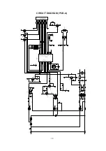
Page 18: ...18 CIRCUIT DIAGRAM PCB A ...
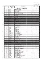
Page 21: ...21 ...


