14
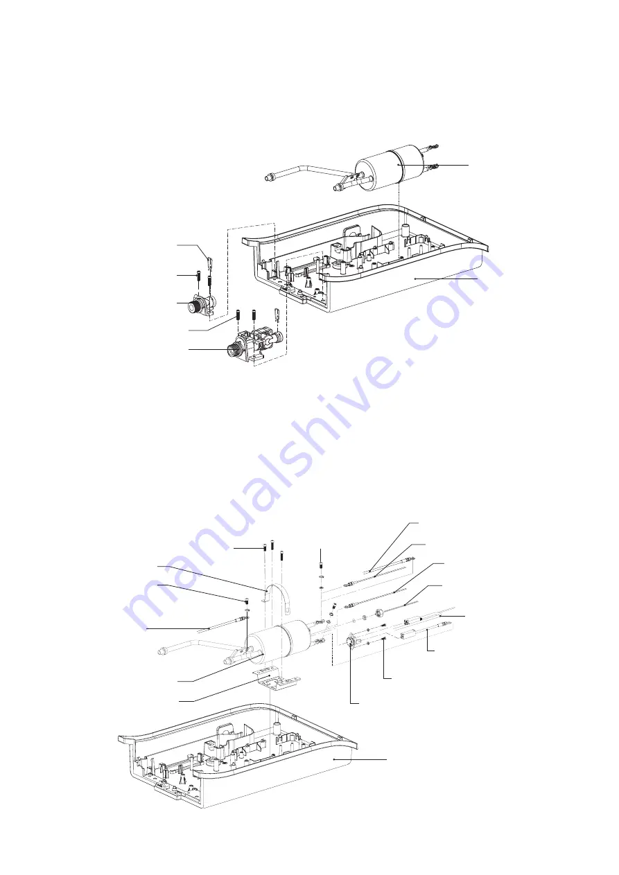
1. Remove the triac in accordance with “REMOVE OF TRIAC”.
2. Remove the body valve ass’y and the water outlet in accordance with “REMOVE OF BODY VALVE
ASS’Y and WATER OUTLET”.
3. Remove the screw to L-Wire Earth from heater tank ass’y.
4. Remove the screw holding cable tie from the heater tank support.
5. Remove 2 screws holding triac lead wire (brown) and thermostat lead wire (yellow) to the
heater tank ass’y.
6. Remove 2 screws holding the thermostat to the heater tank ass’y.
7. Remove the thermistor ass’y from the heater tank ass’y.
8. Now the heater tank ass’y is free.
REMOVE OF HEATER TANK ASS’Y
Fig. 27
Back cover
Thermostat lead
wire yellow
Screw
Screw
L-wire earth
Lead wire brown
Lead wire yellow
Thermistor ass’y
Breaker lead
wire black
Triac lead wire brown
Screw
Screw
Cable tie
Heater tank support
Heater tank
Thermostat
REMOVE OF BODY VALVE ASS’Y AND WATER OUTLET
1. Remove the body in accordance with “REMOVE OF BODY”.
2. Remove the reed SW. in accordance with “REMOVE OF REED SWITCH”.
3. Remove the push SW. set in accordance with “REMOVE OF PUSH SWITCH SET”.
4. Detach 2 clamping springs holding the body valve ass’y and the water outlet to the heater tank ass’y.
5. Remove 2 screws holding the body valve ass’y.
6. Remove 2 screws holding the water outlet.
7. Now the body valve ass’y and the
water outlet are free.
Heater tank
Water outlet
Screw
Clamping spring
Body valve ass’y
Back cover
Screw
Fig. 26
Summary of Contents for WH-237DP
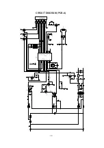
Page 18: ...18 CIRCUIT DIAGRAM PCB A ...
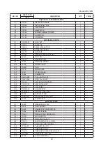
Page 21: ...21 ...


