5-10
VL-H870U
VL-H875U
VL-H890U
VL-H870U
VL-H875U
VL-H890U
(3) Lower drum ass'y
Tighten the FPC mounting screw to the lower drum ass'y. The screw
tightening torque must be 0.08N·m (tighting torque 0.8kg·cm). (Fig-
ure 6)
(4) Upper drum ass’y
After fitting the gap shim which was removed when the upper drum
ass'y was dismantled to the shaft of lower drum ass’y, fit the upper
drum ass’y. (Figure 3)
At this time slightly turn the upper drum ass'y by hand to ascertain that
RTr does not scrape. If scrape is found, replace the gap shim with the
gap shim packaged together with the replacement upper drum ass’y.
(5) Drum motor stator
Fit the motor stator to the shaft. Then, apply the preliminary pressure
0.07N·m (0.7kg) to the motor stator, tighten the stator mounting
screw. The tightening torque must be 0.15N·m (1.5kg·cm).
Install the stator so that the chassis line is nearly parallel with the
motor stator straight section when it is installed on the chassis.
(Figure 9)
(6) Drum base
Align the positioning pin, and tighten the screws (3 pcs.).
(7) Drum ass’y
Install the drum ass’y on the main chassis, and tighten the screws (3
pcs.).
(8) Tape guide
Align the positioning pin, and tighten the screw (one pc.).
Motor stator
Stator set
screw
Motor stator
circuit board
Arrange parallel.
FPC
Chassis line
Figure 9
5-5-5. Phase matching
The phase of the following parts must be matched as
shown in the figure below.
(Ascertain that the marks and round holes align.)
(1) Lo relay gear
(2) Main cam
(3) Sub-cam
(4) Mode switch
Lo relay gear
Phase
alignment mark
(Round hole)
Phase alignment
mark ( Mark)
Phase alignment mark
(Round hole)
Mode switch
5-6. MECHANISM ASSEMBLING METHOD
a
B
T arm guide
Segment gear
M-function lever
Move claw
to rear side.
Move claw to
rear side.
(1) Adjust the phase of each part.
(2) Install screws and washers.
(3) Install the segment gear, T arm guide and the M-function
lever. Install the eject lever.
Item
Tightening torque
Quantity
a S Tight M1.4 x 3
70mN·m (0.7kgf·cm)
1
B ø0.8-ø3-t0.2
1
Summary of Contents for VL-H870U
Page 46: ...VL H870U VL H875U VL H890U 4 1 3 2 LOCATION MAP 3 4 S R Q P O N M L K J 8 3 ...
Page 50: ...VL H870U VL H875U VL H890U 8 7 S R Q P O N M L K J 4 1 3 2 LOCATION MAP 3 4 RIMOCON JACK UNIT ...
Page 54: ...VL H870U VL H875U VL H890U S R Q P O N M L K J 4 1 3 2 LOCATION MAP 3 4 8 11 LCD PANEL ...
Page 58: ...VL H870U VL H875U VL H890U S R Q P O N M L K J 4 1 3 2 LOCATION MAP 3 4 8 15 ...
Page 64: ...VL H870U VL H875U VL H890U 8 21 S R Q P O N M L K J 4 1 3 2 LOCATION MAP 3 4 ...
Page 67: ...VL H870U VL H875U VL H890U 8 24 10 11 12 13 14 15 16 17 18 19 ...
Page 70: ...VL H870U VL H875U VL H890U 8 27 S R Q P O N M L K J 4 1 3 2 LOCATION MAP 3 4 ...
Page 74: ...VL H870U VL H875U VL H890U 8 31 S R Q P O N M L K J 4 1 3 2 LOCATION MAP 3 4 ...
Page 77: ...VL H870U VL H875U VL H890U 8 34 10 11 12 13 14 15 16 17 18 19 ...
Page 80: ...VL H870U VL H875U VL H890U 8 37 S R Q P O N M L K J 4 1 3 2 LOCATION MAP 3 4 ...
Page 83: ...VL H870U VL H875U VL H890U 8 40 10 11 12 13 14 15 16 17 18 19 ...
Page 85: ...VL H870U VL H875U VL H890U 8 42 10 11 12 13 14 15 16 17 18 19 ...
Page 88: ...VL H870U VL H875U VL H890U 8 45 S R Q P O N M L K J 4 1 3 2 LOCATION MAP 3 4 ...
Page 92: ...VL H870U VL H875U VL H890U S R Q P O N M L K J 4 1 3 2 LOCATION MAP 3 4 8 49 ...
Page 95: ...VL H870U VL H875U VL H890U 8 52 10 11 12 13 14 15 16 17 18 19 ...
Page 97: ...VL H870U VL H875U VL H890U 8 54 10 11 12 13 14 15 16 17 18 19 ...
Page 100: ...VL H870U VL H875U VL H890U S R Q P O N M L K J 4 1 3 2 LOCATION MAP 3 4 8 57 ...
Page 103: ...VL H870U VL H875U VL H890U 8 60 10 11 12 13 14 15 16 17 18 19 ...
Page 105: ...VL H870U VL H875U VL H890U 8 62 10 11 12 13 14 15 16 17 18 19 ...
Page 107: ...VL H870U VL H875U VL H890U 8 64 10 11 12 13 14 15 16 17 18 19 ...
Page 109: ...VL H870U VL H875U VL H890U 8 66 10 11 12 13 14 15 16 17 18 19 ...
Page 112: ...A B C D E F G H I J 1 2 3 4 5 6 7 8 9 10 VL H870U VL H875U VL H890U 10 2 Wiring Side SIDE A ...
Page 114: ...A B C D E F G H I J 1 2 3 4 5 6 7 8 9 10 VL H870U VL H875U VL H890U 10 4 Wiring Side SIDE B ...
Page 116: ...A B C D E F G H I J 1 2 3 4 5 6 7 8 9 10 VL H870U VL H875U VL H890U 10 6 Wiring Side SIDE A ...
Page 118: ...A B C D E F G H I J 1 2 3 4 5 6 7 8 9 10 VL H870U VL H875U VL H890U 10 8 Wiring Side SIDE B ...
Page 120: ...A B C D E F G H I J 1 2 3 4 5 6 7 8 9 10 VL H870U VL H875U VL H890U 10 10 Wiring Side SIDE A ...
Page 122: ...A B C D E F G H I J 1 2 3 4 5 6 7 8 9 10 VL H870U VL H875U VL H890U 10 12 Wiring Side SIDE B ...
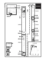
Page 125: ...A B C D E F G H I J 1 2 3 4 5 6 7 8 9 10 VL H870U VL H875U VL H890U 10 15 Wiring Side SIDE A ...
Page 126: ...A B C D E F G H I J 1 2 3 4 5 6 7 8 9 10 VL H870U VL H875U VL H890U 10 16 Wiring Side SIDE B ...