5-5
VL-H870U
VL-H875U
VL-H890U
VL-H870U
VL-H875U
VL-H890U
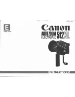
5-4. ADJUSTMENT OF MECHANISM TAPE TRAVEL SYSTEM
5-4-1. Preparation for adjustment
Tape travel system (Figure 1)
,,
,,
,,
,,,,
,,,,
,,,,
,,,,
,,,,
Drum
Reel
Tension pole
Si roller
Sup GR
Sup tilted pole
Tu tilted pole A
Tu GR
Tu tilted pole B
Capstan shaft
Tu guide
Pinch roller
5-4-2. Adjusting the Sup GR and Tu GR
(1) Turn the Sup and Tu guide rollers to get the flat waveform at the inlet and outlet sides.
Inlet side
Outlet side
(a) Normal
(b) Inlet side
waveform is disturbed.
(c) Outlet side
waveform is disturbed.
Figure 2
5-4-3. Adjusting the Si roller height
After replacement of Si roller preset and adjust the Si roller
height.
(1) Si roller height presetting
Adjust the height from the upper surface ofmechanism chas-
sis to the upper surface of lower flange with the aid of jig. Then
lower it by 90
°
(clockwise).
Upper flange
Lower
flange
Height adjusting jig
Master plane
(JiGMP-MX7U)
Upper flange (A)
Si roller
REV mode
Lower flange (B)
Tape must be free from foldeng.
(2) Adjusting the Si roller
1 Playback the tape to set the V/SR mode.
2 Ascertain that the tape is not folded on the lower flange (B) of Si roller. (Figure 4)
If tape folding is found, turn the upper flange (A) of Si roller with the driver (clockwise) to eliminate the folding.
3 Playback the alignment tape (VR2ABOPS).
4 Adjust the Sup GR and Tu GR by the procedure described in section 4-2 above.
5 After V/S F,R perform playback so as to ascertain that the waveform rises horizontally within 2 seconds.
6 Unless the normal waveform is obtained (Figure 5), turn counterclockwise the upper flange (A) of Si roller, and repeat the step
(5) above. Repeat the steps (5) and (6) until the normal waveform is obtained. At this time ascertain that the inlet travel does
not change in the normal playback state. If any change is found, adjust the Sup GR, and redo the step (5).
Figure 3
Rise waveform
REV
OK
Playback
REV
NG
Playback
Figure 4
Figure 5
(1) Clean the tape running areas (guide poles, rollers, drum,
Capstan shaft, Pinch roller) (Figure 1)
(2) Connect the oscilloscope to the following TPs.
RF output ..... TL7406
H-SW-P ....... TL7446
GND ............. TL7452
(3) Playback the alignment tape (VR2ABOPS).
(4) Ascertain that each guide is free from remarkable curl.
(5) Ascertain that the RF waveform of inlet and outlet sides is flat
on the oscilloscope (Figure 2, (a)). Unless the waveform is
flat, (Figure 2, (b), (c)), make an adjustment as follows.
Summary of Contents for VL-H870U
Page 46: ...VL H870U VL H875U VL H890U 4 1 3 2 LOCATION MAP 3 4 S R Q P O N M L K J 8 3 ...
Page 50: ...VL H870U VL H875U VL H890U 8 7 S R Q P O N M L K J 4 1 3 2 LOCATION MAP 3 4 RIMOCON JACK UNIT ...
Page 54: ...VL H870U VL H875U VL H890U S R Q P O N M L K J 4 1 3 2 LOCATION MAP 3 4 8 11 LCD PANEL ...
Page 58: ...VL H870U VL H875U VL H890U S R Q P O N M L K J 4 1 3 2 LOCATION MAP 3 4 8 15 ...
Page 64: ...VL H870U VL H875U VL H890U 8 21 S R Q P O N M L K J 4 1 3 2 LOCATION MAP 3 4 ...
Page 67: ...VL H870U VL H875U VL H890U 8 24 10 11 12 13 14 15 16 17 18 19 ...
Page 70: ...VL H870U VL H875U VL H890U 8 27 S R Q P O N M L K J 4 1 3 2 LOCATION MAP 3 4 ...
Page 74: ...VL H870U VL H875U VL H890U 8 31 S R Q P O N M L K J 4 1 3 2 LOCATION MAP 3 4 ...
Page 77: ...VL H870U VL H875U VL H890U 8 34 10 11 12 13 14 15 16 17 18 19 ...
Page 80: ...VL H870U VL H875U VL H890U 8 37 S R Q P O N M L K J 4 1 3 2 LOCATION MAP 3 4 ...
Page 83: ...VL H870U VL H875U VL H890U 8 40 10 11 12 13 14 15 16 17 18 19 ...
Page 85: ...VL H870U VL H875U VL H890U 8 42 10 11 12 13 14 15 16 17 18 19 ...
Page 88: ...VL H870U VL H875U VL H890U 8 45 S R Q P O N M L K J 4 1 3 2 LOCATION MAP 3 4 ...
Page 92: ...VL H870U VL H875U VL H890U S R Q P O N M L K J 4 1 3 2 LOCATION MAP 3 4 8 49 ...
Page 95: ...VL H870U VL H875U VL H890U 8 52 10 11 12 13 14 15 16 17 18 19 ...
Page 97: ...VL H870U VL H875U VL H890U 8 54 10 11 12 13 14 15 16 17 18 19 ...
Page 100: ...VL H870U VL H875U VL H890U S R Q P O N M L K J 4 1 3 2 LOCATION MAP 3 4 8 57 ...
Page 103: ...VL H870U VL H875U VL H890U 8 60 10 11 12 13 14 15 16 17 18 19 ...
Page 105: ...VL H870U VL H875U VL H890U 8 62 10 11 12 13 14 15 16 17 18 19 ...
Page 107: ...VL H870U VL H875U VL H890U 8 64 10 11 12 13 14 15 16 17 18 19 ...
Page 109: ...VL H870U VL H875U VL H890U 8 66 10 11 12 13 14 15 16 17 18 19 ...
Page 112: ...A B C D E F G H I J 1 2 3 4 5 6 7 8 9 10 VL H870U VL H875U VL H890U 10 2 Wiring Side SIDE A ...
Page 114: ...A B C D E F G H I J 1 2 3 4 5 6 7 8 9 10 VL H870U VL H875U VL H890U 10 4 Wiring Side SIDE B ...
Page 116: ...A B C D E F G H I J 1 2 3 4 5 6 7 8 9 10 VL H870U VL H875U VL H890U 10 6 Wiring Side SIDE A ...
Page 118: ...A B C D E F G H I J 1 2 3 4 5 6 7 8 9 10 VL H870U VL H875U VL H890U 10 8 Wiring Side SIDE B ...
Page 120: ...A B C D E F G H I J 1 2 3 4 5 6 7 8 9 10 VL H870U VL H875U VL H890U 10 10 Wiring Side SIDE A ...
Page 122: ...A B C D E F G H I J 1 2 3 4 5 6 7 8 9 10 VL H870U VL H875U VL H890U 10 12 Wiring Side SIDE B ...
Page 125: ...A B C D E F G H I J 1 2 3 4 5 6 7 8 9 10 VL H870U VL H875U VL H890U 10 15 Wiring Side SIDE A ...
Page 126: ...A B C D E F G H I J 1 2 3 4 5 6 7 8 9 10 VL H870U VL H875U VL H890U 10 16 Wiring Side SIDE B ...