4. Replacing the top cabinet
Install the top cabinet in the reverse order of removing. Before install-
ing, make sure that each connector is connected securely. (The con-
nector of cable
2
and
3
between the MAIN PWB and KEY I/F PWB
are of lock type. When connecting, check the lock of the connector.)
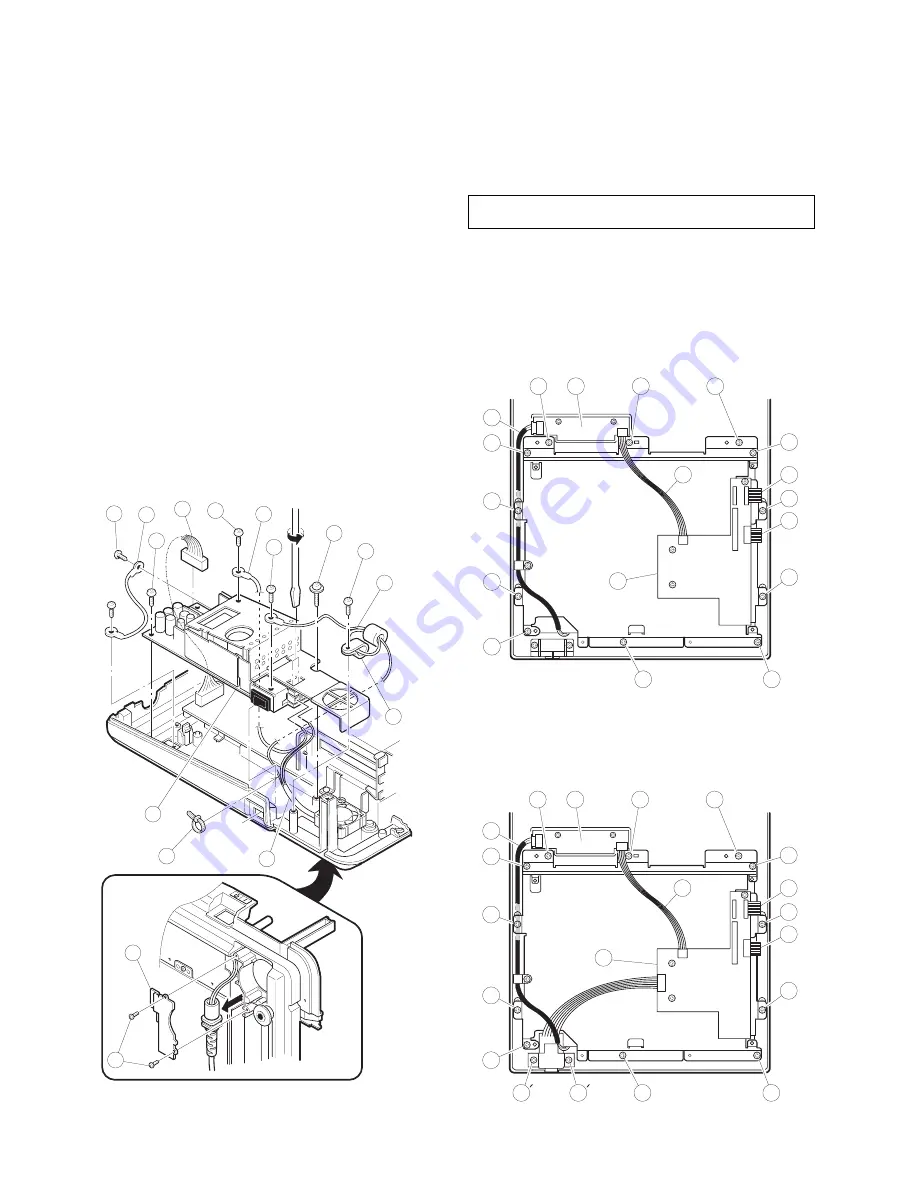
5. Removing the power supply unit
and AC cord
1) Removing the two screws
1
.
2) Removing the AC cord cover
2
.
3) Use a minus screwdriver to loosen the AC cord fixing screws (2
pcs.) of the power supply unit.
4) Remove the AC cord band
3
from the AC cord
4
.
5) Remove the screw
5
and the earth wire
6
of the AC cord
4
.
6) Remove the screw
H
and the cable holder
I
.
7) Pull out the AC cord
4
from the power supply unit.
8) Remove the two screws
7
and the two earth wires
8
.
9) Remove the two screws
9
.
10) Remove the power supply cable
F
.
11) Remove the power supply unit
G
.
6. Replacing the power supply unit
and AC cord
Install the in the power supply unit and AC cord in the reverse order
of removing.
Before installing, make sure that each connector is connected se-
curely.
*
When connecting the AC cord to the power supply unit in
assembly, tighten with the torque of 3 kg/cm
±
1 kg/cm.
7. Removing the LCD unit
1) Remove the Top cabinet from the Bottom cabinet.
2) (For "U" and "A" version)
Remove the LCD angle from the Top cabinet.
Remove 12 screws
1
shown below.
(For "V" version)
Remove the Clerk switch from the Top cabinet.
Remove 2 screws
1
′
shown below.
Remove the LCD angle from the Top cabinet.
Remove 12 screws
1
shown below.
2
1
3
4
5
9
8
7
6
8
9
13
12
11
10
7
LCD Angle
1
4
1
1
1
1
3
5
1
1
7
1
1
1
1
6
1
8
LCD Angle
1
1
1
3
4
1
1
1
5
7
1
1
1
1
1
1
6
8
1
1
– 3 –


