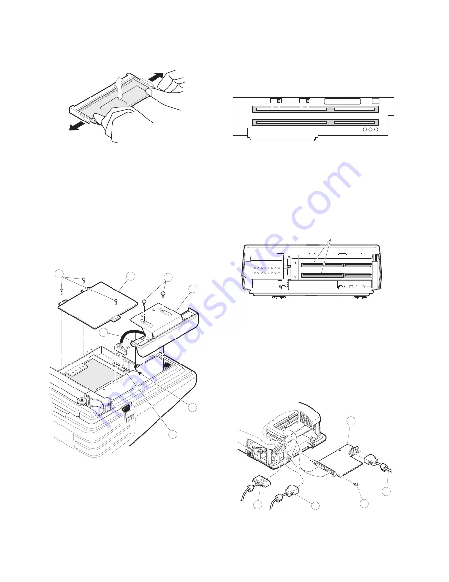
6) Remove the option D-RAM disk.
a) Open the arms of D-RAM connector right and left.
b) The D-RAM disk will be lifted automatically.
12. MCR UNIT: UP-E12MR
1) Fix the MCR ANGLE
1
to the lower cabinet with two screws
2
.
2) Remove the three screws
3
.
3) Remove the HDD COVER
4
.
4) Connect the MCR CABLE
5
to the MCR CONNECTOR: CN18
6
on the MAIN PWB.
5) Fit the MCR cable
5
to the slit part A of the bottom cabinet to
install the HDD cover
4
.
6) Fix the three screws
3
.
13. Adjusting the IRQ10/11 on the ISA
PWB.
Adjust the IRQ10 and IRQ11 using the switches: S1 and S2 on the
ISA PWB if an option equipment is connected to the ISA slot of the
ISA PWB.
S1 = IRQ10: 1 = ON (Connect IRQ10 to the ISA Slot.)
3 = OFF (Connect IRQ10 to GND, not to the ISA Slot.)
S2 = IRQ11: 1 = ON (Connect IRQ11 to the ISA Slot.)
3 = OFF (Connect IRQ11 to GND, not to the ISA Slot.)
14. RS232 & CENTRO I/F: ER-A8RS
*
Adjust the IRQ10 and IRQ11.
(See the "13. Adjusting the IRQ10/11 on the ISA PWB.")
1) Remove the REAR COVER.
2) Remove the screw
1
from the ISA BUS SHASSIS.
3) Insert the I/F PWB
2
to the ISA BUS CONNECTOR.
4) Fix the I/F BRACKET to the ISA BUS SHASSIS with screw
1
.
*
Only one ER-A8RS can be installed.
5) Connect the RS232
3
and CENTRONICS
4
cables to the I/F
PWB.
3
4
2
1
5
A
6
S2
1
3
S1
1
3
ER-A8RS connection
2
3
1
3
4
– 7 –


