4-22
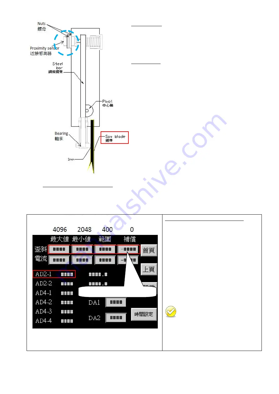
Deviation Dectector Side Section
How to Adjust
1.
Loosen the nuts.
2.
Adjust the proximity sensor until the blade deviation
value shown the display returns to zero.
3.
Tighten the nuts.
How to Check
Put a thick ruler (0.1mm) between saw blade and
deviation roller for measurement. Also, check the
deviation tilt value; it should be 0.1mm. If not 0.1mm,
please adjust the value of compensatory till as same value
as the value of tilt and the thick ruler, 0.1mm. (Please refer
to the next page, picture A.)
Adjust the proximity sensor until the blade deviation
displayed on the control panel is zero.
If the deviation value not changed when adjusting the
proximity sensor or bearing, it means the deviation
detector with malfunction. Need to replace a new
one.
Please clean the internal shell of deviation detector
sometimes for keeping dry and clean.
Picture A :
Deviation Default Value
Before shipping:
Make the proximity sensor connect
with power & adjust the proximity
sensor until the blade deviation
displayed on the control panel is 0 mm
& AD2-1 value as 2048.
Adjust saw arm until AD2-1 value as
2048.
This page for system parameters.
Password is required.
All parameters have been set up by
the manufacturer. In order to prevent
random change from being made to these
parameters and affect cutting precision and
machine life, this function is protected with
a set of password.
Deviation Default Value
the value of
compensatory
Summary of Contents for SW-180NC
Page 1: ...SW 180NC Instruction Manual Version 1 20180619 ...
Page 2: ......
Page 8: ......
Page 13: ...1 5 Illustration Emergency Stop Emergency Stop ...
Page 15: ...1 7 Illustration Safety Labels SW 180NC SafetyLabels ...
Page 20: ...2 4 FLOOR PLAN Machine top view ...
Page 21: ...2 5 Machine front view Machine side view ...
Page 22: ......
Page 66: ......
Page 67: ...6 1 Section 5 ELECTRICAL SYSTEM ELECTRICAL DIAGRAMS ...
Page 68: ......
Page 69: ...SW 180NC CONTROL PANEL LAYOUT ...
Page 70: ...SW 180NC CIRCUIT BOARD LAYOUT ...
Page 71: ...SW 180NC POWER SUPPLY LAYOUT ...
Page 72: ...SW 180NC PLC INPUT OUTPUT LAYOUT ...
Page 73: ...6 1 Section 6 HYDRAULIC SYSTEM HYDRAULIC DIAGRAMS ...
Page 74: ...SW 180NC Hydraulic Circuit 2015 03 23 ...
Page 96: ......
Page 97: ...TOTAL ASSEMBLY 10_2 SW 180NC ...
Page 98: ...3 9 10 16 13 15 12 8 7 11 4 5 1 2 17 6 18 20 21 19 14 Base assembly 10_3 SW 180NC ...
Page 104: ...13 14 18 19 7 10 17 9 3 11 2 1 4 8 15 12 5 6 16 C470H 20000固定床面組 10_9 SW 180NC ...
Page 114: ...4 16 1 15 8 10 7 6 3 5 13 12 11 2 14 17 9 C470H 31000 鋸臂組 Saw arm assembly 10_19 SW 180NC ...
Page 123: ......
Page 124: ......
Page 125: ......
Page 126: ......


