7-3
4. Tooth pitch
The main factor here is the contact length of the blade in the workpiece.
If it is 4P, 25.4 ÷ 4 P = 6.35 mm, that is, one tooth is 6.35 mm.
If it is 3P, 25.4 ÷ 3 P = 8.46 mm If the number is small, it means that the tooth is large.
What is written as 3/4 is that it is a variable pitch of large (3) / small (4).
The saw blade must contact the cutting material at least two pitches. In the case of a thickness of 15 mm,
4P = OK, 3P = NG.
The surface conditions will also affect the cutting rate. If there are places on the surface on
the material which are hard, a slower blade speed will be required or blade damage may
result.
It will be slower to cut tubing than to cut solids, because the blade must enter the material
twice, and because coolant will not follow the blade as well.
Tough or abrasive materials are much harder to cut than their machinability rating would
indicate.
Tooth spacing is determined by the hardness of the material and its thickness in cross
section.
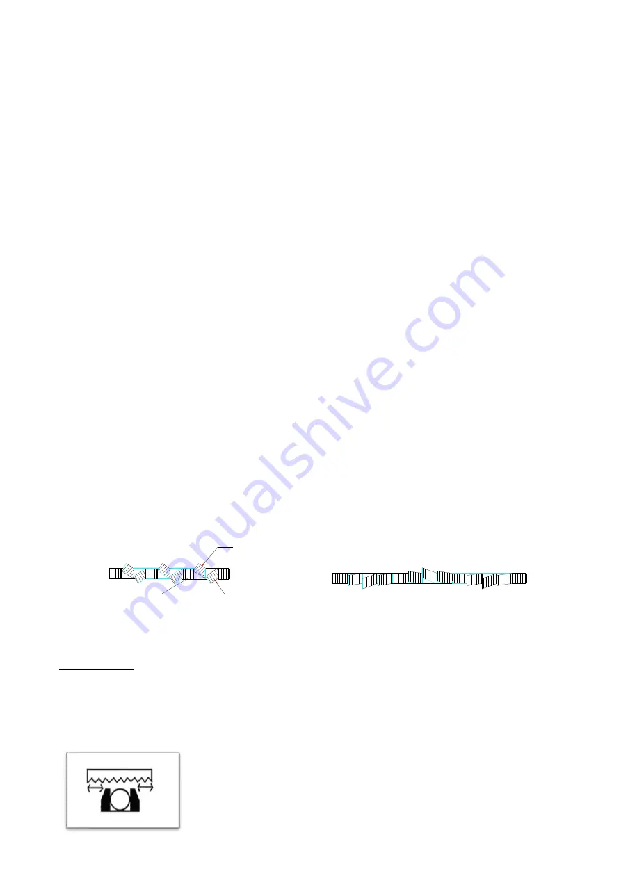
Tooth set prevents the blade from binding in the cut. It may be either a "regular set" (also
called a "raker set" ) or a "wavy set".
The regular or raker set is most common and consists of a pattern of one tooth to the left,
one tooth to the right, and one which is straight, or unset. This type of set is generally used
where the material to be cut is uniform in size and for contour cutting.
Wavy set has groups of teeth set alternately to right and left, forming a wave-like pattern.
This reduces the stress on each individual tooth, making it suitable for cutting thin material
or a variety of materials where blade changing is impractical. Wavy set is often used where
tooth breakage is a problem. This is shown in Fig. 7.2 as follows:
Right
Straight
Left
Regular (raker) Set
Wavy Set
Fig. 7.2 The Saw Set
VISE LOADING
The position in which material is placed in the vise can have a significant impact on the cost per cut.
Often, loading smaller bundles can mean greater sawing efficiency.
When it comes to cutting odd-shaped material, such as angles, I-beams, channel,
and tubing, the main point is to arrange the materials in such a way
that the blade cuts through as uniform a width as possible throughout the entire
distance of cut.
Summary of Contents for SW-180NC
Page 1: ...SW 180NC Instruction Manual Version 1 20180619 ...
Page 2: ......
Page 8: ......
Page 13: ...1 5 Illustration Emergency Stop Emergency Stop ...
Page 15: ...1 7 Illustration Safety Labels SW 180NC SafetyLabels ...
Page 20: ...2 4 FLOOR PLAN Machine top view ...
Page 21: ...2 5 Machine front view Machine side view ...
Page 22: ......
Page 66: ......
Page 67: ...6 1 Section 5 ELECTRICAL SYSTEM ELECTRICAL DIAGRAMS ...
Page 68: ......
Page 69: ...SW 180NC CONTROL PANEL LAYOUT ...
Page 70: ...SW 180NC CIRCUIT BOARD LAYOUT ...
Page 71: ...SW 180NC POWER SUPPLY LAYOUT ...
Page 72: ...SW 180NC PLC INPUT OUTPUT LAYOUT ...
Page 73: ...6 1 Section 6 HYDRAULIC SYSTEM HYDRAULIC DIAGRAMS ...
Page 74: ...SW 180NC Hydraulic Circuit 2015 03 23 ...
Page 96: ......
Page 97: ...TOTAL ASSEMBLY 10_2 SW 180NC ...
Page 98: ...3 9 10 16 13 15 12 8 7 11 4 5 1 2 17 6 18 20 21 19 14 Base assembly 10_3 SW 180NC ...
Page 104: ...13 14 18 19 7 10 17 9 3 11 2 1 4 8 15 12 5 6 16 C470H 20000固定床面組 10_9 SW 180NC ...
Page 114: ...4 16 1 15 8 10 7 6 3 5 13 12 11 2 14 17 9 C470H 31000 鋸臂組 Saw arm assembly 10_19 SW 180NC ...
Page 123: ......
Page 124: ......
Page 125: ......
Page 126: ......


