background image

14

E

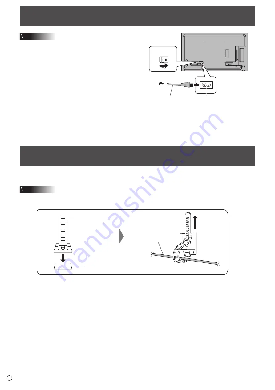
Connecting the Power Cord

Caution

•  Use only the power cord supplied with the monitor.

1. Turn off the main power switch.

2. Plug the power cord (supplied) into the AC input terminal.

3. Plug the power cord (supplied) into the AC power outlet.

Main power switch

1

AC input terminal

Power cord

(Supplied)

For power outlet

2

3

Binding Cables

Cable clamp 

(affixing type)

Affixing point

Cable

The supplied cable clamps (affixing type) can be used to clamp the power cord and cables connected to the back of the monitor.

Caution

•  Attach the supplied cable clamps to a flat surface. Do not attach over a vent.

•  Remove any dust or dirt before attaching.

Summary of Contents for PN-Y326

Page 1: ...PN Y556 PN Y496 PN Y436 PN Y326 LCD MONITOR OPERATION MANUAL ...

Page 2: ...ORTANT To aid reporting in case of loss or theft please record the product s model and serial numbers in the space provided The numbers are located in the rear of the product Model No Serial No U S A ONLY ...

Page 3: ...ctions in the literature accompanying the product WARNING FCC Regulations state that any unauthorized changes or modifications to this equipment not expressly approved by the manufacturer could void the user s authority to operate this equipment NOTE This equipment has been tested and found to comply with the limits for Class A digital device pursuant to Part 15 of the FCC Rules These limits are d...

Page 4: ...people from stepping on them or objects from resting on them 10 The LCD panel used in this product is made of glass Therefore it can break when the product is dropped or applied with impact Be careful not to be injured by broken glass pieces in case the LCD panel breaks 11 Overloading Do not overload AC outlets or extension cords Overloading can cause fire or electric shock 12 Entering of objects ...

Page 5: ...e radio interference in which case the user may be required to take adequate measures 2 Batteries shall not be exposed to excessive heat such as sunshine fire or the like 3 To prevent injury this apparatus must be securely attached to the floor wall in accordance with the installation instructions To maintain compliance with EMC regulations use shielded cables to connect to the following terminals...

Page 6: ...into your outlet consult an electrician for replacement of the obsolete outlet 10 Protect the power cord from being walked on or pinched particularly at plugs convenience receptacles and the point where they exit from the apparatus 11 Only use attachments accessories specified by the manufacturer 12 Use only with the cart stand tripod bracket or table specified by the manufacturer or sold with the...

Page 7: ...ire or malfunction Please request a cleaning of the inside of the monitor from an authorized SHARP servicing dealer or service center Images cannot be rotated on this monitor When using in portrait orientation you will need to prepare appropriately orientated content in advance The AC outlet shall be installed near the equipment and shall be easily accessible The Power Cord Use only the power cord...

Page 8: ...ide the monitor rises this could lead to a malfunction Do not place the monitor on a device which generates heat Adhere to the following when installing the monitor in its portrait orientation Failing to adhere to the following may cause malfunctions Install the monitor such that the power LED is located on the top side Set the THERMAL SENSOR SETTING on the SETUP menu to PORTRAIT See page 29 Be su...

Page 9: ...heral Equipment 12 Connecting the Power Cord 14 Binding Cables 14 Setting the USB flash drive cover 15 Attaching the SD memory card cover 15 Attaching the logo sticker 16 Preparing the Remote Control Unit 17 Installing the batteries 17 Remote control operation range 17 Turning Power On Off 18 Turning on the main power 18 Turning power on off 18 Basic Operation 20 Playing the Files in a media 22 Au...

Page 10: ...al See page 13 14 RS 232C input terminal See page 13 15 LAN terminal See page 13 16 SD card slot See page 13 17 D sub input terminal See page 12 18 DVI D output terminal See page 13 19 DVI D input terminal See page 12 20 HDMI input terminal See page 12 21 USB port See page 12 22 Power supply terminal See page 13 23 Anti theft hole A commercially available anti theft lock can be connected The anti ...

Page 11: ... 3 MUTE button See page 20 4 VOL buttons See page 20 BRIGHT buttons See page 20 Cursor control buttons 5 DISPLAY Red button See page 20 6 MODE Green button See page 21 7 INPUT button See page 20 8 MENU button See page 20 9 ENTER button See page 20 10 RETURN button See page 20 11 SIZE Yellow button See page 20 ...

Page 12: ...minal DVI D PC audio input terminal HDMI PC HDMI AV HDMI input terminal PC audio input terminal D SUB RGB PC audio input terminal D SUB COMPONENT D SUB VIDEO AV audio input terminal Media Player USB port SD card slot DVI mode in which the HDMI signal does not include an audio signal 1 HDMI input terminal Use a commercially available HDMI cable conforming to the HDMI standard Set HDMI of INPUT SELE...

Page 13: ...ercially available RS 232 straight cable between these terminals and the computer The following groups of monitors can be connected in a daisy chain connection PN Y556 PN Y496 PN Y436 PN Y326 PN Y555 PN Y475 PN Y425 PN Y325 11 LAN terminal You can control the monitor from a computer on a network by connecting a commercially available LAN cable between this terminal and a network 12 SD card slot In...

Page 14: ...nto the AC power outlet Main power switch 1 AC input terminal Power cord Supplied For power outlet 2 3 Binding Cables Cable clamp affixing type Affixing point Cable The supplied cable clamps affixing type can be used to clamp the power cord and cables connected to the back of the monitor Caution Attach the supplied cable clamps to a flat surface Do not attach over a vent Remove any dust or dirt be...

Page 15: ...re with the provided screw Screw TIPS If the USB flash drive will be attached use a USB flash drive with dimensions no greater than 1 15 16 inch 50 mm L 13 16 inch 20 mm W 1 2 inch 12 mm H Attaching the SD memory card cover 1 Insert the SD memory card into the SD card slot SD card slot 2 Attach the SD memory card cover and secure with the provided screw Screw ...

Page 16: ...can attach the supplied logo sticker on the monitor Refer to the following example to attach the sticker as necessary Example for portrait orientation Example for landscape orientation Attaching the logo sticker ...

Page 17: ...rol unit to liquids and do not place it in an area with high humidity The remote control unit may not work properly if the remote control sensor is under direct sunlight or strong lighting Objects between the remote control unit and the remote control sensor may prevent proper operation Replace the batteries when they run low as this may shorten the remote control s operation range If a fluorescen...

Page 18: ...t the power cord or turn the breaker on off while the main power switch is on For a complete electrical disconnection pull out the main plug Turning Power On Off Turning power on off Press the POWER button to turn the power ON OFF Power LED POWER button Status Status of the monitor Green lit Power on Orange lit Power off Standby mode Green flashing Input signal waiting mode TIPS When the main powe...

Page 19: ...itor is first turned on set the date and time in DATE TIME SETTING of the SETUP menu Be sure to set the date and time TIPS Set the time on a 24 hour basis The clock stops if the main power remains off for about 1 week Approximate time The actual time varies depending on the state of the monitor ...

Page 20: ...ton again to turn the sound back to the previous level 3 MENU Displays and turns off the menu screen see page 27 4 VOL Volume adjustment Pressing or displays the VOLUME menu when the menu screen is not displayed 15 Press or to adjust the volume of the sound If you do not press any buttons for about 5 seconds the VOLUME menu automatically disappears When the input mode is Media Player the volume ca...

Page 21: ...les may be cropped In this case select the optimal screen size using the screen size switching function of this monitor With some software there may be noise or distortion at the edges of the screen This is due to the characteristics of the software and is not a malfunction Depending on the original image size black bands may remain at the edges of the screen 10 MODE Color mode selection Green Eac...

Page 22: ...deo files see SCHEDULE see page 33 TIPS During auto play it is better to turn the power ON OFF using the remote control unit When the power is turned ON OFF using the main power switch it takes a longer time until auto play is started It also takes a longer time for playback to start from POWER SAVE MODE and ON The displayed screen size is as follows Image NORMAL Video Screen size of input mode be...

Page 23: ...ENU USB SD device Title IMG_0832_R JPG Date 11 Apr 2014 Size 1024x768 IMG_0832_R JPG USB flash drive photo IMG_0833_R JPG IMG_0834_R JPG IMG_0835_R JPG IMG_0836_R JPG IMG_0837_R JPG IMG_0838_R JPG IMG_0839_R JPG IMG_0840_R JPG IMG 0 IMG 0841 R 841 R JPG JPG When the selected item is a folder the files in the folder are shown on the right To move to the folder press ENTER When the selected item is ...

Page 24: ...ds Move forward about 10 seconds ENTER Pause the file that is being played To resume playing the paused file press ENTER DISPLAY Switch between Play only the file being played and Play all MODE Select whether the playback order is shuffled or not during continuous playback RETURN End playback n Audio files Move back about 10 seconds Move forward about 10 seconds ENTER Pause the file that is being ...

Page 25: ...llowing settings can be selected None Dissolve Wipe left Wipe right Wipe up Wipe down Box in Box out TIPS Settings other than Slideshow time are not applied during auto play and schedule play n Settings during play Press MENU during playback Configure the desired setting with and ENTER Options Settings when the file list is displayed see the description on the left or Status only when playing vide...

Page 26: ...E AAC 44 1 128 1 WMV7 and WMV8 video coding are not supported and thus video will not appear If it is possible to play only audio only audio will be output 2 If the playable bit rate is exceeded video may not play smoothly In this event convert the bit rate to about 10 Mbps Playing the Files in a media Some files may not play even if the format is supported A maximum of 32 alphanumeric characters ...

Page 27: ...U to display the menu screen SCREEN PICTURE AUDIO SETUP H V POS SIZE RESET 2 Press or to select PICTURE and press ENTER 3 Press or to select CONTRAST and press ENTER SCREEN PICTURE AUDIO SETUP BRIGHT CONTRAST BLACK LEVEL TINT COLORS COLOR ADJUSTMENT RESET 50 4 Press or to adjust the setting and press ENTER SCREEN PICTURE AUDIO SETUP BRIGHT CONTRAST BLACK LEVEL TINT COLORS COLOR ADJUSTMENT RESET 60...

Page 28: ...olor towards magenta and selecting changes it towards green COLORS Adjusts the color intensity SHARPNESS HDMI AV D SUB COMPONENT D SUB VIDEO Adjusts the sharpness of the image COLOR ADJUSTMENT COLOR MODE Changes the color mode on the screen The color mode on the screen can also be changed using a remote control unit See page 21 sRGB is DVI D HDMI PC D SUB RGB input only See page 21 for details WHI...

Page 29: ...und output from the audio output terminals SPEAKER Select whether or not speakers are used LAN Setup Configures the settings to control the monitor from the computer via LAN See page 42 ID SETTING Assigns ID numbers to monitors connected in a daisy chain see page 35 using the RS 232 cables The numbers 0 to 25 are available for ID numbers If 0 is set the system regards this as the state where no ID...

Page 30: ...ve or SD memory card is connected DVI D HDMI D SUB Input mode switching may take 15 seconds or more depending on the connected equipment When there are no signals at any of the input terminals switching is continued until an input signal is detected and the monitor does not enter input signal waiting mode CONNECT AUTO INPUT SELECT DVI D HDMI PC HDMI AV D SUB RGB Sets whether the input into the inp...

Page 31: ...nging the setting to OFF Otherwise there is a risk that data in the connected device will be lost ALL RESET Resets the settings to the factory default settings The settings in LAN SETUP are retained TIPS If COLOR MODE is set to sRGB the following items cannot be set WHITE BALANCE PRESET USER and GAMMA When the COLOR MODE is set to HIGH ILLUMINANCE or VIVID GAMMA can not be adjusted When ENLARGE is...

Page 32: ...cal direction in ENLARGE V 5 Set the section of the separated image to be displayed on each monitor in ENLARGE POS 1 Press ENTER 2 Press or to select position then press MENU ENLARGE POS You can align 4 9 16 or 25 monitors and integrate them into a single large screen to display Enlarged views of separated images are displayed in each monitor 3 1 4 2 2 4 1 3 4 monitors 4 monitors 1 2 3 5 6 7 9 10 ...

Page 33: ...omatic display playback of files in a media Image files and video files can be combined in the same playlist Audio files cannot be used Up to 30 files can be set 1 Select the type of file to be set in the list with or and press ENTER A list of folders or files of the selected type Photo Video appears 2 Select a file with or and press ENTER to set the file When a file is selected and set it appears...

Page 34: ...dulinglist txt in the USB flash drive or the SD memory card The displayed screen size is as follows Image NORMAL Video Screen size of input mode before schedule playback To have schedule playback always play at the same size set the screen size of each input mode to the same size nScreen display for adjustment Before making adjustments in the SCREEN menu or PICTURE menu display an image to brighte...

Page 35: ... length of the cable used and the surrounding environment To COM port Computer First monitor Second monitor RS 232C output terminal RS 232C output terminal RS 232C input terminal RS 232C input terminal RS 232 straight cables commercially available Communication conditions Set the RS 232C communication settings on the computer to match the monitor s communication settings as follows Baud rate 9600b...

Page 36: ...When one of the following commands is used INPS ASNC POWR nCommunication interval After OK or ERR is returned you must send the following commands To set a timeout for the command response specify 10 seconds or longer When connecting multiple monitors in a daisy chain set the timeout to at least the product of the monitor s position from the computer multiplied by 10 seconds Example 3rd monitor fr...

Page 37: ...t command is for the monitor with ID number 2 WAIT Searching for monitor with ID number 2 OK 002 Found monitor with ID number 2 VOLM0030 Sets volume of monitor with ID number 2 to 30 WAIT Processing OK 002 OK response from monitor with ID number 2 VOLM0020 Sets volume to 20 OK 001 The volume of the monitor with ID number 1 the one directly connected to the computer is set to 20 The IDSL command is...

Page 38: ...by all the connected monitors If you want to determine that a value has been returned by a specific set assign ID numbers to each monitor in advance When some monitors do not return their responses the probable cause is that the monitors could not receive the command or command processing is not complete Do not send a new command Example When 4 monitors are connected and assigned ID numbers 1 thro...

Page 39: ... 4 D SUB VIDEO 9 HDMI AV 10 HDMI PC 11 Media Player R 1 DVI D 2 D SUB RGB 3 D SUB COMPONENT 4 D SUB VIDEO 9 HDMI AV 10 HDMI PC 11 Media Player 1 1 If power standby mode is entered when the input mode is Media Player the input terminal that was used prior to switching to Media Player will respond not Media Player SCREEN menu Function Command Direction Parameter Reply Control Response contents SIZE ...

Page 40: ... and spaces cannot be entered Telnet USERNAME USER WR XXXXXXXX XXXXXXXX X Eight characters or less half width alphanumeric characters and _ The field can be left blank but spaces cannot be entered Telnet PASSWORD PASS WR XXXXXXXX XXXXXXXX X Eight characters or less half width alphanumeric characters and _ The field can be left blank but spaces cannot be entered ID SETTING ID NO SETTING IDST W 0 25...

Page 41: ...abnormal has occurred and backlight brightness is dimmed 4 Temperature sensor abnormal TEMPERATURE ACQUISITION ERRT R Value Returns the temperature at the temperature sensors in the following format Sensor 1 CAUSE OF LAST STANDBY MODE STCA W 0 Initialization R 0 No detectable error has occurred 1 Standby mode by POWER button 3 Standby mode by RS 232C or LAN 4 Input signal waiting mode by No Signal...

Page 42: ...pecify the DNS server address if the DHCP CLIENT is set to OFF If you are not using a DNS server specify 0 0 0 0 NETWORK NAME Enter the device name Controlling the Monitor with a computer LAN FTP SETTING Specify this setting to copy auto play files see page 22 from your computer over LAN to a USB flash drive or SD memory card connected to the monitor using Content Distributor For information on co...

Page 43: ...and password The default settings are blank 2 Send commands to control the monitor The commands used are the same as those for RS 232C Refer to the communication procedure see page 35 for operation Usable commands are provided in the RS 232C command table see page 39 3 Disconnect the connection with the monitor and quit the function 1 Send BYE When the transmission is successful goodbye is returne...

Page 44: ... this monitor See page 49 Control buttons do not work There is no picture Load noises from outside may be interfering with normal operation Turn off the power and turn it on after waiting at least 5 seconds and then check the operation The monitor makes a cracking sound You may occasionally hear a cracking sound from the monitor This happens when the cabinet slightly expands and contracts accordin...

Page 45: ...itor enters standby mode due to a rise in temperature to return to normal display turn the power switch off and then back on again The monitor however will enter standby mode again if the cause of the temperature rise is not eliminated See page 8 Check whether the monitor is placed at a location where a quick rise in temperature is likely Internal temperature rises quickly if the vents on the moni...

Page 46: ...nt AC 100 240 V 1 2 A 50 60 Hz AC 100 240 V 1 0 A 50 60 Hz AC 100 240 V 0 9 A 50 60 Hz AC 100 240 V 0 8 A 50 60 Hz Operating temperature 2 32 F to 104 F 0 C to 40 C Operating humidity 20 to 80 no condensation Power consumption Input signal waiting mode 3 standby mode 4 105W 7 0W 8 0W 87W 7 0W 8 0W 76W 7 0W 8 0W 69W 7 0W 8 0W Dimensions excluding protrusions inch mm Approx 48 9 16 W x 1 13 16 D x 2...

Page 47: ... 8 9 5 24 1 4 616 5 5 8 15 5 12 5 8 320 3 8 9 5 3 8 9 5 3 8 9 5 21 5 8 548 5 5 8 15 5 7 3 4 197 8 203 7 3 4 197 8 203 11 16 17 2 1 16 52 11 1 8 282 5 3 8 9 5 3 8 9 5 3 8 9 5 19 482 5 3 16 4 11 16 17 3 16 4 5 5 8 15 5 7 3 4 197 8 203 1 7 8 47 8 7 16 214 5 7 16 10 5 7 16 10 5 7 16 10 5 14 1 4 362 25 5 8 15 5 3 7 16 88 4 7 16 112 When mounting the monitor be sure to use a wall mount bracket that comp...

Page 48: ...reen Power consumption Monitor ON Display 105 W 87 W 76 W 69 W Active OFF No display 7 0 W 7 0 W 7 0 W 7 0 W Values of the PN Y556 PN Y496 PN Y436 and PN Y326 in that order from the top nDDC plug and play The monitor supports the VESA DDC Display Data Channel standard DDC is a signal standard for plug and play between monitors and computers Information about resolution and other parameters is exch...

Page 49: ... 79 5MHz 83 5MHz 108 0MHz 108 0MHz 135 0MHz 85 5MHz 121 75MHz 106 5MHz 162 0MHz 154 0MHz 74 4MHz 85 383MHz 148 5MHz 28 3MHz Yes Yes Yes Yes Yes Yes Yes Yes Yes Yes Yes Yes Yes Yes Yes Yes Yes Yes Yes Yes Yes Yes Yes Analog D SUB Yes Yes Yes Yes Yes Yes Yes Yes Yes Yes Yes Yes Yes Yes Yes Yes Yes Yes Yes Yes Yes Yes Yes Yes DVI D HDMI Yes Yes Yes Yes Yes Yes Yes Yes Yes Yes Yes Yes Yes Yes Yes Yes ...

Page 50: ...Green video signal input 10 GND 3 Blue video signal input 11 N C 4 N C 12 DDC data 5 N C 13 Hsync signal input 6 GND for red video signal 14 Vsync signal input 7 GND for green video signal 15 DDC clock 8 GND for blue video signal nHDMI input terminal pins HDMITM Connector No Function No Function 1 TMDS data 2 11 TMDS clock shield 2 TMDS data 2 shield 12 TMDS clock 3 TMDS data 2 13 CEC 4 TMDS data ...

Page 51: ... plug detection 5 N C 17 TMDS data 0 6 DDC clock 18 TMDS data 0 7 DDC data 19 TMDS data 0 5 shield 8 N C 20 N C 9 TMDS data 1 21 N C 10 TMDS data 1 22 TMDS clock shield 11 TMDS data 1 3 shield 23 TMDS clock 12 N C 24 TMDS clock nRS 232C output terminal pins D sub 9 pin No Function No Function 1 N C 6 N C 2 Received data 7 N C 3 Transmitted data 8 N C 4 N C 9 N C 5 GND ...

Page 52: ...bracket must be installed on a wall which can endure at least 4 times or more the weight of the monitor Install by the most suitable method for the material and the structure Do not use an impact driver When moving the monitor hold the parts marked by below Do not hold the LCD panel This may cause product damage failure or injury After mounting please carefully ensure the monitor is secure and not...

Page 53: ...PN Y556 Y496 Y436 Y326 M EN16J 1 ...

Reviews: