


-
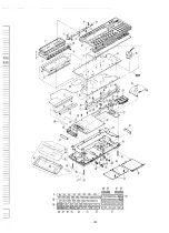
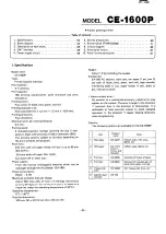
PC-1600
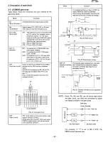
4. CMT interface
The CMT interface
consists
of the following
circuits:
•
Write circuit
•
Read circuit
•
Remote
circuit
4-1. Write circuit
As shown
below,
the
logic level signals
are converted
into
signals of micro
level.
•
High
frequency
component
of
signal
is eliminated.
~
ILow pass filter I
•
As a 3KHz
component
drops
6dB than
a 1.5KHz
com-
ponent
because
of the
low pass filter,
compensation
is
therefore
done.
~lBfU!1
frequency
compensation
I
•
The
outout
level is
set
to the micro
level. ~IAttenuation
I
•
DC component
is cut. ~~~~
CMTOUT
4.7VPP
=
vcc
L"..IU1Il
N\I\~
~.5mvpp
• Low pass fi Iter
• High frequency
compensation
• Attenuation
• OC decoupling
MIC
3mVRMS
Rl
C2
CMTOUT~7µF
Cl
R2
MIC
6.8Kn
R3 ~
680n
~~~
Low pass
High
Attenuation
filter
frequency
compensation
Cl, C2: DC decuppling
Output
level: 3mV rms
Output
impeadance:
APROX
600n
4-2. Read circuit
1MU
EAR
I
I
CONTRO
L
..J
Inside gatearray
The read signal amplifier
circuit
consists
of the same type as
that
of the
CE-150.
The
circuitry
is contained
inside
the
gate array
in the case of the CE-1600P.
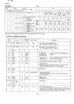
4-3. Remote circuit
For
the
relay
(AG8229
or
G5AK-287P)
is a two-coil
latching
type,
A ON
(or OFF") pulse
must
be given to the
activate
(or deactive)
the
relay
through
the
driver
of the
gate arrav,
in order
to turn the relay active.
(See Fig.8.)
The width
of pulse must
be more
than
5 milliseconds
than
that
mentioned
in the
relay
specification.
With
the
CE-
1600P,
it is set to about
10 milliseconds.
The
following
signal
formats
are
used
for
the
cassette
interfacing
signals.
Write
PWM method
(1600
method)
Read
PWM method
(1600
method)
and
1500 method
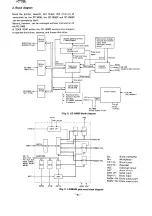
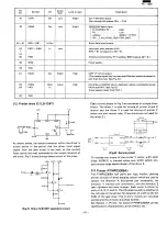
5. Power supply circuit
5-1. Power supply
VP, VBAT,
and battery
recharge
circuits
01
RM-l0Z
(x2)
02
03
AC Adaptor
About 8.4V
.. "
liIoI
~
,
..
VP (6.4V)
RK-13
AAx5
:
D6
11OQ03(lA)
x
2
1
For
prevention
of
reverse
current
to the
rechar-
geable
battery
to the adaptor.
To
achieve
efficient
recharging
of the
batterv,
a
Schottky
barrier
type diode
R K-13 (1.7 A) is
used.
02,03:
These
diodes
are used to drop the voltage
from the
printer
to less than
printer
driving
voltage
(7.15V
01 :
04:
max.).
F or prevention
of reverse
current
from
VP to the
rechargeable
batterv,
when
the
adaptor
is being
used.
For
prevention
of
reverse
current
from
V BAT
(PC·1600)
to VP (printer).
The diode
is a Schottky
battery
type
for avoiding
battery
exhaustion
when
the adaptor
is used,
To
avoid
exhaustion
of the
battery
in the
main
unit
when
the
rechargeable
battery
is used,
06
is
used to bypass
04 and 05.
To meet
the printer
drive voltage
(5.0V,
min.),
the
rechargeable
battery
low voltage
is set to 5.65V
lirnit (1.13V
per batterv
l.
After
the main
unit battery
is ORed with the VBAT supply
from
the
CE-1600P,
VCC
is regulated
to
4.7V
before
supplied
to the CE-1600P.
(See the figure
below.)
When
the
main
unit
power
is turned
off,
VCC is not sup-
plied.
05:
06:
CE-1600P
PC-1600(Main unit)
VCC4-~r------r----------------~
vcc
±
UM-3
1;
(x4)
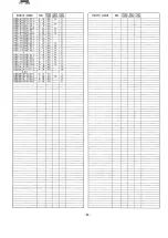
Summary of Contents for PC-1600
Page 42: ... 11 CIRCUIT DIAGRAM PARTS POSITION KEY P W B LCD SIDE 39 ...
Page 43: ...PC l600 40 ...
Page 44: ...PC 1000 KEY P W B LSI SIDE 41 ...
Page 45: ... 42 ...
Page 48: ... PC l600 F P C P W B 45 ...
Page 49: ... Kn 46 ...
Page 52: ... PC l600 CONNECTOR P W B 49 ...
Page 53: ... 50 ...
Page 55: ... __ PC l600 tli I ONLY Pc 1600K I I 1 I 52 l J ...
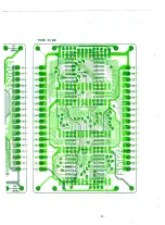
Page 56: ... PC l600 K MEMORY P W B ROM Cut c IJ O lJ1F C O lJ1F I Bend capacitor to inward ROM SIDE 53 ...
Page 57: ...RAM SIDE 54 ...
Page 61: ...I I 2 3 4 42 58 ...
Page 93: ... P W B LSI SIDE t 90 ...
Page 117: ... PC I600 ...


