-
PC-1600
I
Reference
I
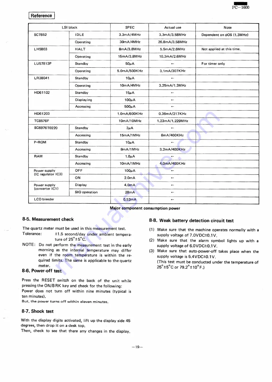
LSI block
SPEC
Actual use
Note
SC7852
IDLE
3.3mA/4MHz
3.3mA/3.58MHz
Dependent on q,OS (1.3MHz)
Operating
3OmA/4MHz
26.8mA/3.58MHz
LH5803
HALT
8mA/3.8MHz
5.5mA/2.6MHz
Not applied at this time.
Operating
l5mA/3.8MHz
10.3mA/2.6MHz
LU578l3P
Standby
50µA
+-
For tim er only
Operating
5.0mA/500KHz
3.lmA/307KHz
LR38041
Standby
10µA
+-
Operating
10mA/4MHz
3.25mA/l.3MHz
HD6l102
Standby
15µA
+-
Displaying
100µA
+-
Accessing
500µA
....
HD6l203
1.0mA/600KHz
O.36mA/217KHz
TC8576F
10mA/l0MHz
1.23mA/l.229MHz
SC6976T0220
Standby
3µA
....
Accessing
15mA/1MHz
6mA/400KHz
P'ROM
Standby
10µA
+-
Accessing
8mA/1MHz
3.2mA/400KHz
RAM
Standby
1.0µA
+-
Accessing
10mA/1MHz
4.0mA/400KHz
Power supply
OFF
100µA
<-
(IC regulator IC3)
ON
2.0mA
....
Power supply
Display
4.0mA
+-
(converter ICl )
SIO operation
28mA
....
LCD bleeder
O.52mA
+-
Major component consumption
power
8-5. Measurement check
8-8. Weak battery detection circuit test
The quartz meter must be used in this measurement
test.
Tolerance:
±1.5 second/day
under ambient tempera-
ture of 25°±5°C.
NOTE:
00 not perform the measurement
test in the early
morning
as the internal
temperature
may differ
even if the room temperature
is within
the re-
quired limits. The same is applicable to the quartz
meter.
8-6. Power-off test
(1) Make sure that the machine operates normally with a
supplv
voltage of 7 .0VDC±0.1 V.
(2)
Make sure that
the alarm symbol
lights
up
with a
supply voltage of 6.0VDC±0.1 V.
(3)
Make sure that
auto-power-off
takes place when the
supply voltage is 5.4 V DC±O.l V.
(This test must be conducted
under the temperature
of
25°±5°C
or 79.2°±10°F.)
Press the
RESET switch on the back of the unit while
pressing the ON/B RK key and check for the following:
Power does not turn
off within nine minutes
(typical is
ten minutes).
But. the power
turns
off within
eleven
minutes.
8-7. Shock test
With the display digits activated,
lift up the display side 45
degrees, then drop it on a desk top.
Then, check to see that there any changes in the displav,
-19-
Summary of Contents for PC-1600
Page 42: ... 11 CIRCUIT DIAGRAM PARTS POSITION KEY P W B LCD SIDE 39 ...
Page 43: ...PC l600 40 ...
Page 44: ...PC 1000 KEY P W B LSI SIDE 41 ...
Page 45: ... 42 ...
Page 48: ... PC l600 F P C P W B 45 ...
Page 49: ... Kn 46 ...
Page 52: ... PC l600 CONNECTOR P W B 49 ...
Page 53: ... 50 ...
Page 55: ... __ PC l600 tli I ONLY Pc 1600K I I 1 I 52 l J ...
Page 56: ... PC l600 K MEMORY P W B ROM Cut c IJ O lJ1F C O lJ1F I Bend capacitor to inward ROM SIDE 53 ...
Page 57: ...RAM SIDE 54 ...
Page 61: ...I I 2 3 4 42 58 ...
Page 93: ... P W B LSI SIDE t 90 ...
Page 117: ... PC I600 ...