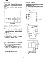
The reason why the reset signal is required at power on is to
hold it in the standby mode so as to avoid malfunction
in
the floppy disk controller inside the floppy disk unit.
4-3.
Regulated power supply circuit
~--------------------~
5VB
Fig. 3 Regulated power supply circuit
Fig.3 shows the regulated
voltage supply
circuit.
In this
circuit, floppy
disk unit's
5VC (SV of amp) is supplied
from VP (battery
voltage), because SVC can not be sup-
plied from VCC on account of current restriction,
For the voltage of SVC is used with a voltage difference of
0.5V
minimum
against
VCC, the power is produced
in
reference to 5V B through
the differentiation
circuit
corn-
posed of TR2 and TR3, not merely the regulator circuit.
SV B is a transistor output wh ich is employed to turn on/off
VCC with the MOTOR ON signal, and it has less voltage
drop caused in the transistor,
as compared with VCC, So,
Dl
is inserted to the outpur
voltage feedback
transistor
TR3 to correct 5VC to be 0.2 to 0.3 volts higher then 5VB
in appearance. (A schottky barrier diode is used for 01.)
CO N 1
~OP
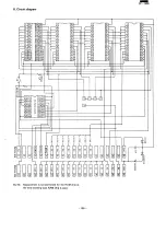
6. Circuit diagram and parts positions
26 TNIF
D 7
1
27
VGG
o
6
2
28
M 1
o
5
3
29 Cl K
04
4
3C
P T
o
3
5
31
P U
o
2
6
32
P V
o
1
7
ß
F G N 0
o
0
8
FGNO
R S T N 9
35
A 8
A 7
,0
3Ii
A 9
A 6
'1
37
A 10
A 5
12
:Jl
A 11
A 4
13
39
A 12
A 3
4
.40 A 13
A 2
15
41 A 14
A 1
16
A 15
A
0
17
14<
B F 0 M R E 0 18
loIA
IOR~
107 N 19
14~WA I T
n~
146
ITfi
R1i
21
147 G N 0
G NO
2
l4t!
V~
GND
3
149 V
p
Vec
4
se
V
p
V"
5
CO
N1
5.
Brief description of floppy disk drive
-
PC-l600
The floppy disk controller
is implemented
within the 2.S"
floppy
disk drive, and the floppy
disk driving and head
seeking are done by one motor. The floppy disk is driven
by the belt and the head is seeked using the solenoid and
cam.
The floppy
disk controller
and
its peripheral
logic are
contained
in a single chip gate array (2700 gates) and the
read/write
amplifier
is also in a single chip LSI, which are
directly bus connected to permit a low voltage driving.
Floppy
disk format
and write method
are unique to the
floppy disk. Though the floppy disk drive is for one-sided
operation,
both sides of the media can be used.
Specification
of FDU 250
1) Memory capacity:
64KB (512 Bytes/sector,
8 sectors/track)
2) Recording method:
GCR (4/5)
3) Transfer speed:
250K bits (25K Bytes/sec)
4) Track density:
48TPI
5) Total tracks:
16
6) Revolutions:
270 rpm
7) Access time:
One step 80 milliseconds from track 00 to track 15.
170 milliseconds to restore from track 15 to track 00.
Settling time:
SO milliseconds
8) Motor startup time:
0.5 second
NOTE:
GCR is an abbreviation
of of Group Coded Re-
cording. A single byte, 8 bits, data are divided into
two 4-bit data which is also converted onto a 5-bit
data. Thus, a single byte (8 bits) is recorded on the
media as a 10-bit data.
CO N 2
8
R1
L1 = 1S1SBELl
-
--
-
-100-
Summary of Contents for PC-1600
Page 42: ... 11 CIRCUIT DIAGRAM PARTS POSITION KEY P W B LCD SIDE 39 ...
Page 43: ...PC l600 40 ...
Page 44: ...PC 1000 KEY P W B LSI SIDE 41 ...
Page 45: ... 42 ...
Page 48: ... PC l600 F P C P W B 45 ...
Page 49: ... Kn 46 ...
Page 52: ... PC l600 CONNECTOR P W B 49 ...
Page 53: ... 50 ...
Page 55: ... __ PC l600 tli I ONLY Pc 1600K I I 1 I 52 l J ...
Page 56: ... PC l600 K MEMORY P W B ROM Cut c IJ O lJ1F C O lJ1F I Bend capacitor to inward ROM SIDE 53 ...
Page 57: ...RAM SIDE 54 ...
Page 61: ...I I 2 3 4 42 58 ...
Page 93: ... P W B LSI SIDE t 90 ...
Page 117: ... PC I600 ...


