


4-1.
Relation of the main CPU-1 to the main
CPU·2
Since two CPUs are linked together,
the bus line of one
CPU is on the sytem bus; the other CPU bus is kept in the
floating state.
Shown in the following table are the bus signals of the two
CPUs in connection.
SC7852 signal name
Z-80 signal name
LH·5803
signal name
A15 - AO
A15 - AO
A15 - AO
OS7 - OBO
07 - 00
07 - 00
MREQ
Opposite polarity
MEO
of MREQ
10RQ
Opposite polarity
ME1
of IORQ
RO
RO
00*
WR
WR
R!W
*
The 00 output
of the LH·5803
is connected
to
RD
of
the SC7852 via the gate array (LR38041).
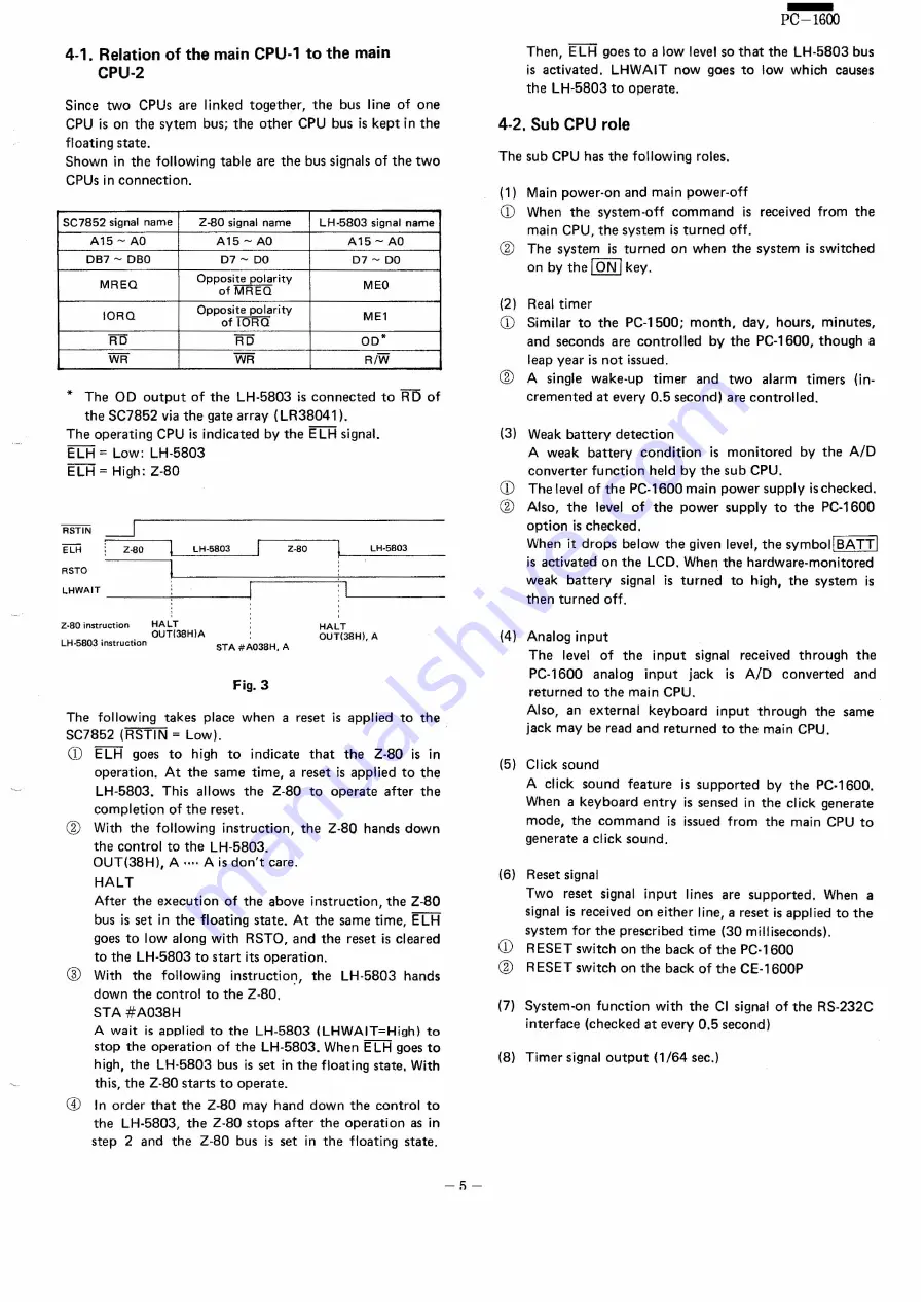
The operating CPU is indicated by the ELH signal.
ELH
=
Low: LH·5803
ELH
=
High: Z·80
Z-80
LH·5803
LH-5803
Z-80
RSTO
LHWAIT
___
--;...
_J
Z·BO instruction
HALT
OUT(38H)A
LH·5B03
instruction
HALT
OUT(38H),
A
STA #A03BH,
A
Fig.3
The following takes place when areset
is applied to the
SC7852 (RSTIN
=
Low).
CD
E LH goes to high to
indicate
that
the
Z·80
is in
operation.
At the same time, areset
is applied to the
LH·5803.
This allows the Z·80
to operate
after the
completion
of the reset.
@
With the following instruction,
the Z·80
hands down
the control to the LH·5803.
OUT(38Hl, A .... Ais don't care.
HALT
After the execution
of the above instruction,
the Z-80
bus is set in the floating state. At the same time, ELH
goes to low along with RSTO, and the reset is cleared
to the LH·5803 to start its operation.
®
With the following
instruction,
the
LH·5803
hands
down the control to the Z·80.
STA #A038H
A wait
is applied to the LH·5803
(LHWAIT=High)
to
stop the operation
of the LH-5803. When E LH goes to
high, the LH·5803
bus is set in the floating state, With
this, the Z·80 starts to operate.
CD
In order that the Z·80
may hand down the control to
the LH·5803,
the Z·80 stops after the operation
as in
step 2 and the Z·80
bus is set in the floating state.
-!')-
-
PC-1600
Then, ELH goes to a low level so that the LH·5803
bus
is activated.
LHWAIT now goes to low which causes
the LH·5803
to operate.
4-2.
Sub CPU role
The sub CPU has the following roles.
(1) Main power-on and main power-oft
CD
When the svstern-off
command
is received from the
main CPU, the system is turned off.
@
The system is turned on when the system is switched
on by the ION I key.
(21 Real timer
CD
Similar to the PC·1500;
month,
day, hours, minutes,
and seconds are controlled
by the PC·1600,
though a
leap year is not issued.
@
A single wake-up
timer
and two
alarm
timers
(in-
cremented at every 0.5 second) are controlled.
(3) Weak battery detection
A weak battery
condition
is monitored
by the A/D
converter function held by the sub CPU.
CD
The level of the PC·1600 main power supply is checked.
@
Also, the level of the power supply to the PC-1600
option is checked.
When it drops below the given level, the symboilBATTI
is activated on the LCD, When the hardware-monitored
weak battery
signal is turned
to high, the system is
then turned off.
(4) Analog input
The
level of the
input
signal received through
the
PC·1600
analog
input
jack
is A/D
converted
and
returned to the main CPU.
Also, an external
keyboard
input
through
the same
jack may be read and returned to the main CPU.
(5) Click sound
A click sound feature
is supported
by the PC·1600.
When a keyboard entry is sensed in the click generate
mode, the command
is issued from the main CPU to
generate a click sound.
(6) Reset signal
Two reset signal input
lines are supported.
When a
signal is received on either line, areset
is applied to the
system for the prescribed time (30 milliseconds).
CD
RESET switch on the back of the PC·1600
@
RESET switch on the back of the CE·1600P
(7) System-on function
with the CI signal of the RS·232C
interface (checked at every 0.5 second)
(8) Timer signal outout
(1/64
sec.)
Summary of Contents for PC-1600
Page 42: ... 11 CIRCUIT DIAGRAM PARTS POSITION KEY P W B LCD SIDE 39 ...
Page 43: ...PC l600 40 ...
Page 44: ...PC 1000 KEY P W B LSI SIDE 41 ...
Page 45: ... 42 ...
Page 48: ... PC l600 F P C P W B 45 ...
Page 49: ... Kn 46 ...
Page 52: ... PC l600 CONNECTOR P W B 49 ...
Page 53: ... 50 ...
Page 55: ... __ PC l600 tli I ONLY Pc 1600K I I 1 I 52 l J ...
Page 56: ... PC l600 K MEMORY P W B ROM Cut c IJ O lJ1F C O lJ1F I Bend capacitor to inward ROM SIDE 53 ...
Page 57: ...RAM SIDE 54 ...
Page 61: ...I I 2 3 4 42 58 ...
Page 93: ... P W B LSI SIDE t 90 ...
Page 117: ... PC I600 ...


