-38
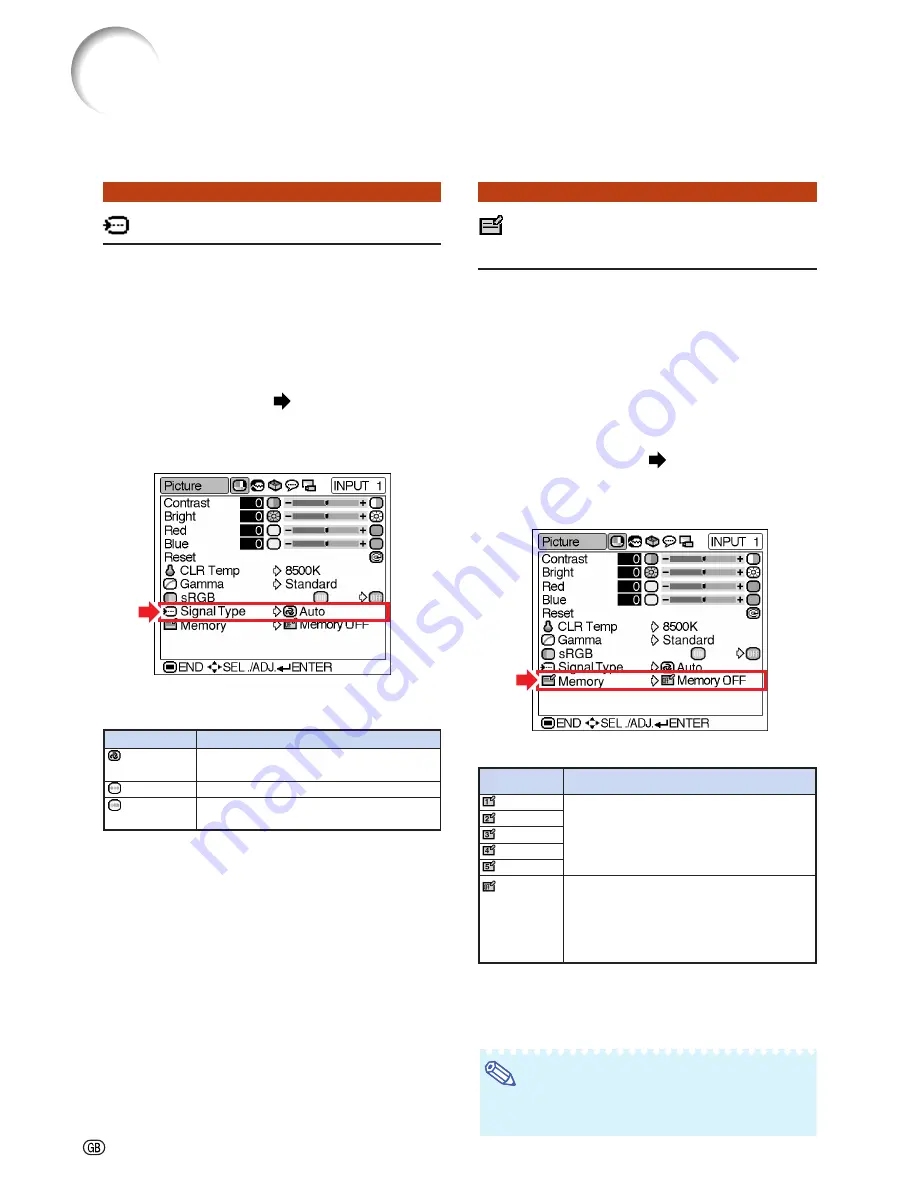
Signal Type
(Signal Type Setting)
The signal type setting is preset to “Auto”;
however, in rare cases a clear picture may not
be displayed. In that case, select “RGB” or “Com-
ponent” in accordance with the input signal.
Select “Signal Type” on the “Picture” menu
and set it to “Auto”, “RGB” or “Component”
for INPUT 1.
Setting the menu screen
Page
34
Example: “Picture” screen menu for
INPUT 1 (RGB) mode
Description of Signal Type Settings
Memory
(Storing and Selecting
the Adjustment Settings)
Use this function to store the adjustment settings
on the “Picture” menu. No matter which input
mode or signal type is selected, you can select
and apply the settings you have stored in a
memory location.
Select “Memory” on the “Picture” menu and
the memory location where you want to store
the settings. Then adjust the setting items
on the “Picture” menu.
Setting the menu screen
Page
34
Example: “Picture” screen menu for
INPUT 1 (RGB) mode
Description of Memory Positions
If you want to apply the stored settings on
the “Picture” menu, select “Memory” on the
“Picture” menu and the memory location
where you have stored the settings.
Note
•
You can change the stored settings after se-
lecting the memory location for those settings.
Description
Input signals are automatically
recognized as RGB or Component.
Set when RGB signals are received.
Set when Component signals are
received.
Selectable settings
Auto
RGB
Component
Description
Settings of all items on the “Picture”
menu can be stored in memory location.
The stored settings can be selected in
any input mode.
Besides “Memory 1” to “Memory 5”, other
settings on the “Picture” menu can be
stored for each input mode. The settings
stored in “Memory OFF” cannot be applied
when another input mode is selected.
Memory 1
Memory 2
Memory 3
Memory 4
Memory 5
Memory OFF
Selectable
settings
Picture Adjustment
Summary of Contents for Notevision PG-B10S
Page 82: ...SHARP CORPORATION ...


