Operation Manual (Continued)
English
- 15 -
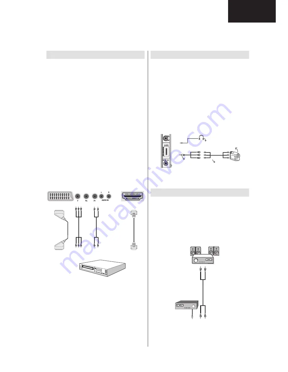
Connecting to a DVD Player
If you want to connect a DVD player to your LCD
TV, you can use connectors of the TV set. DVD
players may have different connectors. Please refer
to your DVD player’s instruction book for additional
information. Power off both the TV and the device
before making any connections.
Note
: Cables shown in the illustration are not
supplied.
If your DVD player has an HDMI socket, you can
•
connect via HDMI. When you connect to DVD player
as illustrated below, switch to HDMI source. See,
“Input Selection” section.
Most DVD players are connected through
•
COMPONENT SOCKETS. Use a component video
cable to connect video input. For enabling audio, use
a component audio cable as illustrated below. When
the connection is made, switch to YPbPr source.
See, “Input selection” section.
You may also connect through the SCART 1 or
•
SCART 2. Use a SCART cable as shown below.
Note
: These three methods of connection perform the
same function but in different levels of quality. It is not
necessary to connect by all three methods.
HDMI
HDMI
inputs
Scart sockets
Component
video
inputs
Component
audio
inputs
DVD Player
Using Side AV Connectors
You can connect a range of optional equipment to your
LCD TV using side connectors of the TV.
For connecting a camcorder or camera , you should
•
use
SIDE
AV
socket (side). To do this, you must use
the supplied
video/audio connection cable
. First,
plug single jack of the cable to the TV’s
AV IN
socket
(side). Afterwards, insert your camera cable’s (
not
supplied
) connectors into the plural part of the
video/
audio connection cable
. Colours of the connected
jacks should match. See illustration below.
Afterwards, you should switch to
•
AV IN
source. See
the section
Input selection
in the following sections
for more information.
Camera
AVConnection
Cable(supplied)
AVCable
(notsupplied)
Headphone
To listen the TV sound from headphones, you
•
should connect headphones to your TV by using the
HEADPHONE
jack as illustrated above.
Using Other Connectors
You can connect a range of optional equipment
to your LCD TV. Possible connections are shown
below. Note that cables shown in the illustration are
not supplied.
For connecting a to a device that has SPDIF support,
•
use an appropriate SPDIF cable to enable sound
connection.
External Speakers
A device that
supports
SPDIF signal.
A01_[GB]_MB70_5112UK_DVBT_C_DLNA_HBBTV_MMH_WIFI_40971LED_GOLD11_10078557_50216773.indd 15
01.05.2012 21:00:07
13
LC-40LS340
Summary of Contents for LC-40LS340E
Page 27: ...11 c Absolute Ratings d Recommended Operating Conditions e Pin Functions 27 LC 40LS340 ...
Page 37: ...21 c BCM3556 Block Diagram 37 LC 40LS340 ...
Page 46: ...LC 32LE340 343 LC 40LE340 343 30 b Pinning 46 LC 40LS340 ...
Page 52: ...LC 32LE340 343 LC 40LE340 343 35 c Pinning 52 LC 40LS340 ...
Page 57: ...39 15 LOW POWER CEC MICROCONTROLLER NEC uPD78F0503 Pinning 57 LC 40LS340 ...
Page 59: ...b Block Diagram 59 LC 40LS340 ...
Page 60: ...LC 32LE340 343 LC 40LE340 343 Figure 8 Pin Diagram 60 LC 40LS340 ...
Page 74: ...LC 32LE340 343 LC 40LE340 343 57 Video Settings Audio Settings 74 LC 40LS340 ...
Page 75: ...58 Options 1 Menu Options 2 Menu 75 LC 40LS340 ...
Page 76: ...LC 32LE340 343 LC 40LE340 343 59 Tuner Settings Menu Source Settings Menu 76 LC 40LS340 ...
Page 77: ...60 Diagnostic Menu 21 General Block Diagram 77 LC 40LS340 ...
Page 78: ...LC 32LE340 343 LC 40LE340 343 NOTES 78 LC 40LS340 ...
Page 100: ...LC 32LE340 343 LC 40LE340 343 NOTES 100 LC 40LS340 ...
Page 121: ...NOTES 121 LC 40LS340 ...


