


2 – 63
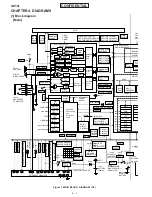
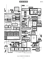
GX10i
CONFIDENTIAL
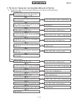
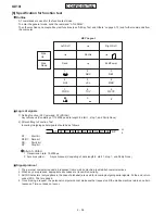
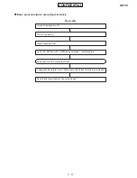
1) Basic Operation Test
<Startup and initial condition>
Fit a battery or a dummy battery in the set. Hold down the “End/Power” key to start up in the general mode. Then enter
AT+XDIAG without pressing any key.
Start up in the general function test mode. (3 sec. until startup)
Back light OFF
After startup, “H/W CHECK
∗
GX-10i
∗
” is displayed.
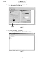
When adjusting by the AT command, be sure to perform the LDDEVPRM command before adjustment and the SVDEVPRM
command after adjustment.
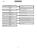
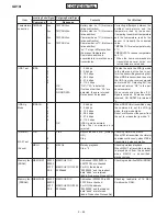
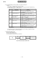
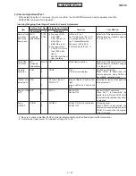
Incoming/Outgoing Serial Signal Format for Basic Operation Test
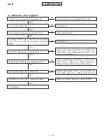
FROM to
SRAM
Checking
LCD back
light voltage
Measuring
RTC clock
Battery
voltage
check
RTC Test
(Writing)
RTC Test
(Reading)
Temperature
A/D
Adjustment
Temperature
check
LDDEVPR
M
LED
OUT32K
BATVAL
RTCWR
RTCRD
TMPAD
TMP
None
5
4
3
2
1
0
1
0
None
yymm
ddhh
mmss
None
4
3
2
1
n
LDDEVPRM OK
LDDEVPRM NG
LEDn (n=0, 1, 2, 3, 4)
OUT32Kn
Okn.nn
OK
RTC yymmddhhmmss
ADSETOK
TMPADH <Readout
AD value>
TMPADL <Readout AD
value>
TMPADRDY
TMPnxx: Temperature
NG: Except 0 – 50 ˚C
FROM to SRAM extension.
The contents of FROM are dam-
aged.
Sub-screen display back light.
Key back light LED.
Red LED lights up.
Green LED lights up.
Main-screen display back light
lights up.
All LEDs light off. *1
32 kHz Output (MON Output)
32 kHz Stop (Returned to
ALT1)
Reading down to the last two
digits of voltage.
Writing time of day
“yymmddhhmmss” to RTC. *2
Reading time of day
“yymmddhhmmss” from RTC.
*2
Adjustment mode ended. *3
2.2 V Measurement started.
0.4 V Measurement started.
Adjustment mode started.
Temperature readout. (0 ˚C
min.)
n=1: Camera
n=2: Battery
Before adjustment perform this
command to output the adjustment
value stored in FROM to SRAM.
Checking that LEDs light up.
LED1: Main-screen display
back light lights up.
LED2: Green LED lights up.
LED3: Red LED lights up.
LED4: Key back light lights up.
LED0: All LEDs light off.
Checking frequency of the real time
clock.
Normal: When OUT32K1 is transmitted,
TP205 frequency is 32.768 kHz
±
1.11
kHz.
Reading the voltage of the battery
power line. BATVAL is transmitted,
“OK” and the voltage value are
returned.
Writing time to the clock.
When RTCWR yymmddhhmmss is
transmitted, yy (year), mm (month),
mm (hour), and ss (minute) are written.
Reading time of the clock. When
RTCRD is transmitted, time of day is
read out.
Refer to the “Adjustment procedures
after replacement of parts” on pages
2 – 36 and 2 – 37.
Reading temperature measured by
the temperature sensor.
When TMP is transmitted, TM and
temperature are returned. In case of
other than 0 – 50 ˚C, “NG” is returned.
Item
Incoming Serial Signal Outgoing Serial Signal
Contents
Test Method
Command
n
Response


