


13
FU-40SE-TA
5) Clock circuit
This generates the clock signal required for operation of the microcomputer LSI-1.
Its frequency is 4MHz which is supplied from the ceramic oscillator CF1.
6) Key input circuit
The key SW1 on the switch PWB K is connected to the resistor R101.
The key status is input into the pin 7 of the microcomputer LSI-1 via the resistor R102 and the ceramosonic
capacitor C101.
Key ON : H, Key OFF : L
7) LED drive circuit
Repetitive signal of " H " and " L " output from the pins 3 - 5 of the microcomputer LSI-1 turns on and off the digital
transistors Q110 - Q112.
They are turned on one by one at intervals of certain time. When " L " is output from the pins 11 - 16 of the
microcomputer LSI1 as they are turned on, the corresponding LED that are connected to them light up.
The LED to display the cluster mode has two colors of super-high-intensity green and blue.
When in the clean mode, " L " is output from the pin 10 of he microcomputer LSI1, Q114 is turned on, and the blue
LED lights up. When in the refresh mode, " L " is output from the pin 9, Q113 is turned on, and the green LED lights
up.
8) Remote control recieve circuit
The infrared signal transmitted from the remote control is received by the reception unit RU1.
When the H/L signal is input into the pin 8 of the microcomputer LSI-1 via the resistor R81 and the ceramosonic
capacitor C83, it is determined from which key the signal was transmitted. C81, C82, and C83 absorb or reduce the
disturbing lights, noise derived from its own power supply circuit, and external noise.
9) Dust sensor circuit
When the pulse signal, which is the dust sensor drive signal, is output from the pin 35 of the microcomputer LSI-1
(input into the pin 3 of the sensor connector CN-F), the dust sensor is activated and the sensor output signal (pin
2 of the sensor connector CN-F) is input into the pin 30 of the microcomputer (A/D conversion terminal) via R62 and
C63.
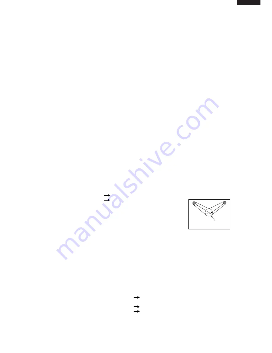
<Principle of dust sensor>
Using the pulse signal input from the microcomputer, the infrared LED inside the dust sensor emits light.
When the light is reflected by the dust that passes through the sensor, it is detected by the internal photo
acceptance unit and smoothed and amplified, and then output from the terminal.
Less dust: less light acceptance
less output (low voltage)
More dust: more light acceptance
more output (high voltage)
<Control>
After turning the power on, the value obtained 20 seconds after starting the first operation (for 30 seconds, the clean
sign of three colors for stabilization is lit one by one) is compared to the initial setting reference value of the
microcomputer.
If it is clean enough, the reference value is revised, and if it is dirtier than the designated level, the clean sign is
changed to the sign that indicates the air is contaminated (orange or red, depending on the level), while the
reference value remains the same.
The value is compared with the reference value in the previous operation and is controlled 20 seconds or more after
the operation is started.
The dust sensor is always activated during operation, and air contamination is checked in every four seconds in
relative comparison between the average value and the reference value.
The clean sign is displayed, the fan motor is controlled or the cluster mode is switched according to the level of
contamination.
Reference value: If the current level is cleaner
the reference valueis is changed to the current value
than the reference value
immediately.
: If the current level is dirtier
the value remains the same.
than the reference value
the reference value is revised when the level becomes
cleaner than that.
The dust sensor is activated only during the operation.
It is deactivated while the operation is stopped to cut down the standby power consumption.
Luminescence side
Receiver
The hole through
which dust passes


