


12
FU-40SE-TA
Circuit diagram
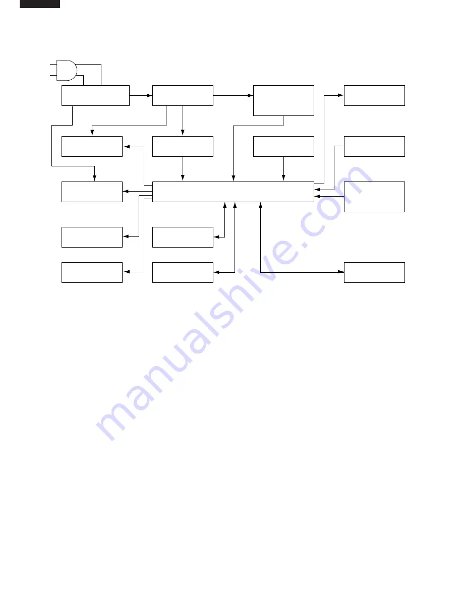
BLOCK DIAGRAM
(2) Circuit description
1) Noise-prevention circuit
This circuit protects the circuit from the external noise and lightning surge coming in from the AC plug, and also
absorbs the noise outgoing from the AC plug. It consists of the film capacitor C1 and C4, varistor VRS1, current
fuse FUSE1, and line filter L1.
2) Power supply circuit
a) Vm: The commercial power supply (AC220-240V) is put through the current fuse FUSE1 and the thermal
fuse, rectified by the diode bridge DB1, and smoothed by the electrolytic capacitor C2.
Then it is supplied as the power input for the fan motor and the hybrid IC (HIC1).
(Vm = approx. DC310 - 340V)
b) VL:
The hybrid IC (HIC1) is activated by the DC input Vm and the external coil L2, and has two output
terminals.
The first output is changed into VL after being smoothed by the electrolytic capacitor C12.
It is used as the power supply for the buzzer drive circuit, fan motor drive circuit, relay RY1, and high-
voltage unit drive SSR1 (VL = approx. DC15V).
c) VDD: The second output is smoothed by the electrolytic capacitor C11 before used as the power supply for
the microcomputer LSI-1, high-voltage unit drive circuit, relay drive circuit, dust/odour sensor circuits,
and LED drive circuit (VDD = approx. DC5V).
3) Power supply clock generation circuit
The voltage between the input terminal to DB1 and its output terminal (GND) is divided by the resistor R21, R22
and R23, and input into the digital transistor Q21.
Then it is converted into the DC square wave signal that has the same frequency with the AC power supply, and
input into the pin 31 on the microcomputer LSI1 via the resistor R25 and the ceramosonic capacitor C22.
The microcomputer LSI-1 considers it as the source signal for time count, and decides the power supply
frequency and controls the output time.
When this signal retains " H " or " L " state for over certain period of time, the microcomputer LSI-1 assumes it
to be a power failure and stops outputs from the fan motor, high-voltage unit, dust/odour sensors, buzzer, and
LED.
4) Reset circuit
If the VDD is lower than specified, " L " is input into the pin 18 of the microcomputer LSI1 to reset LSI-1 using
the circuit consisting of the reset IC (IC2), R31 and C32.
When VDD is higher than specified, " H " is input into the same pin, reset command is canceled, and LSI-1
is started.
12)
13)
11)
14)
1)
4)
2)
3)
7)
9)
10)
15)
5)
6)
8)
Power supply
clock generation
circuit
LED drive
circuit
Buzzer drive
circuit
Relay drive
circuit
High voltage
unit drive circuit
Fan motor
drive circuit
Noise prevention
circuit
Odour sensor
circuit
Dust sensor
circuit
Reset circuit
Power supply
circuit
Clock circuit
EEPROM
circuit
Remote control
signal recieve
circuit
Key input
circuit
LSI 1(Microcomputer)


