background image

18

FU-28H-S

7) LED drive circuit

Repetitive signal of " H " and " L " output from the pins 18 - 20 of the microcomputer LSI-1 turns on and off the
digital transistors Q110 - Q112.
They are turned on one by one at intervals of certain time. When " L " is output from the pins 15 - 17 of the
microcomputer LSI-1 as they are turned on, the corresponding LED that are connected to them light up.
And " L " is output from the pin 11 of the microcomputer LSI-1, Q113 is turned on, the plasmacluster LED turned on blue.

8) Remote control receiving circuit

The infrared signal transmitted from the remote controller is received by the reception unit RU1.
When the H/L signal is input into the pin 23 of the microcomputer LSI-1 via the resistor R81 and the ceramic
capacitor C83, it is determined from which key the signal was transmitted. C81, C82, and C83 absorb or reduce
the disturbing lights, noise derived from its own power supply circuit, and external noise.

9) Odour sensor circuit

The pulse signal, which is the odour sensor drive signal, is output from the pin 41 of the microcomputer LSI-1, and
the odour sensor is pulse-driven on the circuit of Q71, Q72, R73, R74, R76, and C73.
The sensor output signal is input into the pin 29 (A/D conversion terminal) of the microcomputer LSI-1 via R71 and C71.
< Principle of odour sensor >

The metal oxide semiconductor in this sensor reacts to ammonia, hydrogen, and alcohol, and changes the
resistance.

Weak odour : high resistance

_

high voltage

Strong odour : low resistance

_

low voltage

< Control >

After turning the power on, the value obtained 25 seconds after starting the first operation is set as the reference
value and the contamination is decided in relative comparison between the values detected at an interval of
approximately one second and the reference value.
Although the odour sensor is always activated during operation, it is deactivated while the operation is stopped
to cut down the standby power consumption.
However, if it comes to a complete stop, the reading condition is altered in the next operation.
Therefore, it is activated for one minute in every ten minutes to keep the operating conditions.

Reference value : If the current level is cleaner than the reference value

_

the reference value is changed to the current value immediately.

If the current level is dirtier than the reference value and the contamination level changes
(such as suddenly increased odour of cigarette smoke)

_

the reference value remains the same

_

the value in the clean condition is adopted as a new reference value.

If the current level is dirtier than the reference value and the contamination level does not
change (Natural change only)

_

the reference value remains the same.

_

the value in the cleanest condition at eight-minute intervals is adopted as a new
reference value.

10) Buzzer drive circuit

The " H " / " L " signals output from the pin 22 of the microcomputer LSI-1 drive the digital transistor Q51 and
sound the buzzer BZ1.

11) Fan motor drive circuit

The fan motor has four input terminals and one output terminal.

Vm : DC voltage input to be the source of motor rotation. (Vm = approx. DC311-339V)

(FM  7 pin) Vm created by the power supply circuit is directly input and is constantly applied.

GND : Reference of the electric potential. All potentials such as Vm, Vcc, Vs, and PG indicate the

(FM  5 pin) potential differences with GND.

Vcc : DC voltage input terminal to be the power supply for the circuit that is built in the fan motor.

(FM  3 pin) During operation, it turns on Q43 and Q44 by outputting the " H " signal from the pin 21 of the

microcomputer LSI-1, and supplies the potential almost equal to VL to the Vcc terminal (Vcc =
approx. DC15V).

Vs : This input terminal controls the rotation speed of the fan motor (speed instruction signal).

(FM  2 pin) After supplying Vcc during operation, the PWM (x/256

µ

s) pulse is output from the pin 25 of the

microcomputer LSI-1 and smoothed in the circuit consisting of C41, R41-43, Q41 and Q42.
Then it goes through R46 and C43 to supply the DC voltage to the Vs terminal.
(Vs = approx. DC 0 ~ 6V)
When speeding up rotation

: the pulse width X is widened

_

Vs voltage is increased

When slowing down rotation : the pulse width X is narrowed

_

Vs voltage is decreased

PG : Fan motor rotation speed output terminal (feedback signal)

(FM  1 pin) The pulse signal according to the rotation speed is output and it is input into the pin 24 of the

microcomputer LSI-1 via the circuit consisting of R47, R44, R45, and C42.
The microcomputer recognizes the current rotation speed based on this PG signal, and controls
the Vs signal above to keep the speed to the designated level.

Summary of Contents for FU-28H-S

Page 1: ...uld be used SERVICE MANUAL FU 28H S MODEL SHARP CORPORATION Page SAFETY PRECAUTIONS 2 HOW SHARP AIR PURIFIER WORKS 4 SPECIFICATIONS FOR THIS PRODUCT 5 NAMES OF PARTS 7 INSTLLATION 8 ABOUT THE FUNCTION 14 ELECTRIC CIRCUIT 15 TROUBLESHOOTING GUIDE 22 REPLACEMENT OF MAIN PARTS 24 OPERATION 29 MAINTENANCE 30 CUMULATIVE TIME CHECK FUNCTION MAINTENANCE MODE 32 USE RESIN TABLE 33 REPLACEMENT PARTS LIST 3...

Page 2: ... similarly qualified person in order to avoid a hazard Do not operate when using aerosol insecticides or in rooms where there is oily residue incense sparks from lit cigarettes chemical fumes in the air or a humidity condition Use care when cleaning the air purifier Strong corrosive cleansers may damage the exterior Only Sharp Authorized Servicers should service this air purifier Contact the neare...

Page 3: ...drastic temperature changes Place on a stable surface with sufficient air circulation Install the unit on a wall wooden pillar crosspiece etc that is flat and strong enough Do not install the unit on a thin wall or on plasterboard The unit may fall down if installed on an insufficiently strong wall To install the unit on a wooden wall that is less than 10 mm thick consult your dealer and have them...

Page 4: ...rough the filter Odour elements are absorbed by HEPA Filter as well Some odour ingredients absorbed by the filters may become separated and may be discharged through the air outlet and result in additional odour Depending on the usage environment this odour may become strong in a shorter period than expected In this case purchase the optional replacement filter kit FZ 28SEF NOTE The air purifier i...

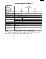
Page 5: ...hours Outside dimension mm 482 W x 142 D x 337 H Weight kg 6 2 Cord length m 2 5 Installation Wall mounting Accessories HEPA filter Active carbon filter remote control 2 AA batteries Wall mounting Kit Wall mounting braket Wood screws 4 Fisher plugs 4 Replace the filter 2 HEPA filter 12 months Active carbon filter 12 months Option Replace filter FZ 28SEF 1 HEPA Filter 1 Active Carbon Filter 1 The s...

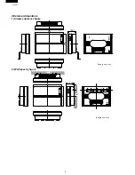
Page 6: ...6 FU 28H S 2 External dimentions 1 Simple substance figure 482 Length unit mm 337 139 5 2 Wall tapestry figure 9 141 5 337 482 Length unit mm Wall Wall Wall Wall Wall Wall ...

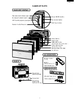
Page 7: ...ton Odour Sensor Filter Frame HEPA Filter white with Microbial Control Filter blue Active Carbon Filter Deodorizing Filter Stainless Steel Pre Filter Front Panel BACK Power Cord Adjusting Guide Power Cord Power Plug ACCESSORIES Remote Control 1 unit Battery R6 AA battery X 2 Operation Manual Wall mounting kit Wall mounting bracket Wood screws 4 pcs Fisher plugs 4 pcs Air Outlet Shape of plug depen...

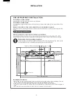
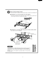
Page 8: ...here is nothing that could obstruct installation of the unit Then fix the wall mounting bracket through screw holes with the supplied wood screws Install the unit on a wall wooden pillar crosspiece or the like that is flat and strong enough If the wall is weak or made of concrete have the unit installed by a specialist such as an electric appliance store Avoid locations near inverter lamps or wher...

Page 9: ...gh Make sure that the unit is installed in an upright position without leaning to the right or left Wooden crosspiece Wall mounting bracket Hole on the wall Fisher plug Wood screw 2 Mount wall mounting bracket Mount the bracket using the included wood screws so that it is maintained level Installation on a concrete block or mortar surface Drill holes of at least 35 mm depth and 5 mm diameter into ...

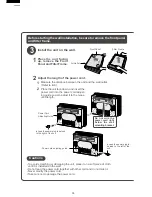
Page 10: ... cloth until it is installed on the wall Do not lead the power cord together with other cord and do not twist it Never modify the power cord Take care not to damage the power cord Front Panel Filter Frame Air Outlet 1 2 3 Install the unit on the wall 1 Place the unit facing up remove the Front Panel and Filter Frame 2 Adjust the length of the power cord 1 Measure the distance between the unit and ...

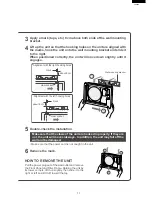
Page 11: ...es 5 Double check the installation Make sure that the claws of the unit are hooked in properly If they are not the unit will move sideways In addition the unit may fall off the wall and be damaged Make sure that the power cord is not caught in the unit 6 Remove the mark Wall mounting bracket HOW TO REMOVE THE UNIT Pull the power plug out of the wall outlet and remove the Front Panel and Filter Fra...

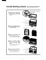
Page 12: ...it will not operate properly 4 Place the Active Carbon Filter within the Filter Frame on top of the HEPA Filter The Active Carbon Filter does not have a front and a back 5 Next place the Pre Filter within the Filter Frame Fit the 4 tabs of the Pre Filter into the holes in the Filter Frame FILTER INSTALLATION Tabs Pre Filter Active Carbon Filter HEPA Filter Filter Frame HEPA Filter Filter Frame Pre...

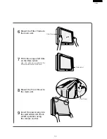
Page 13: ...art date on the Date Label Use the date as a guide for the Filter Replacement schedule 8 Mount the Front Panel to the main unit 9 Insert the power plug into the wall outlet and check on off operation using the remote control Date Label Claw socket Claw Filter Frame Front Panel ...

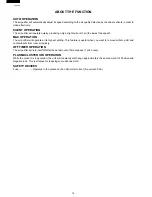
Page 14: ...will operate at its highest setting This feature is useful when you want to remove airborne dirt and contaminants from room air quickly OFF TIMER OPERATION The air purifier will turn itself off after the set amount of time elapses 1 or 4 hours PLASMACLUSTER ION OPERATION While the product is in operation the unit will constantly dischange approximately the same amount of Positive and Negative ions...

Page 15: ...damage to the land of the PWB extreme care should be taken not to leave the bit in contact with the PWB for an extended period of time Remove the bit as soon as a good flow is achieved The high content of tin in lead free solder will cause premature corrosion of the bit To reduce wear on the bit reduce the temperature or turn off the iron when it is not required Leaving different types of solder o...

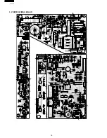
Page 16: ...16 FU 28H S 3 PRINTED WIRING BOARD ...

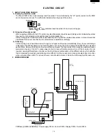
Page 17: ...d as the power supply for the microcomputer LSI 1 plasmacluster unit drive circuit odour sensor circuit and LED drive circuit VDD approx DC5V 3 Power supply clock generation circuit The voltage between the input terminal to DB1 and its output terminal GND is divided by the resistor R21 R22 and R23 and input into the digital transistor Q21 Then it is converted into the DC square wave signal that ha...

Page 18: ...ce value _ the reference value is changed to the current value immediately If the current level is dirtier than the reference value and the contamination level changes such as suddenly increased odour of cigarette smoke _ the reference value remains the same _ the value in the clean condition is adopted as a new reference value If the current level is dirtier than the reference value and the conta...

Page 19: ...D No Operation Operation mode OFF timer Cluster Buzzer Point to be check Fan Cluster Odour Auto Max Silent 4 hours 1 hour ion Silent Max Drive Sensor Green Green Green Green Green Blue PORT No 25 39 41 2 3 4 5 6 1 LED No 1 Turn the power on while holding down Model select memory ON OFF check the OFF TIMER button on the main unit 2 Press the POWER ON OFF button EEPROM version No upper side check on...

Page 20: ...ads turn off The buzzer does not sound f Remedy Please replace the PWB 3 Fan motor rotation speed error a Outline This error mode is activated when the unit detects that the fan motor is locked or the connector is opened b Detection time In all modes during operation c Detection conditions When the unit detects 0 rpm as the rotation speed of the fan motor for 15 consecutive seconds d Abnormality d...

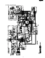
Page 21: ...21 FU 28H S 6 CONTROL CIRCUITDIAGRAM ...

Page 22: ...e clogged There is an obstruction near the air inlet or outlet Undesirable odors that have accumulated in the antibacterial HEPA filter are being released The air purifier is being used near a light that uses an inverter or lighting is old and is flickering The air purifier is being in a location where it is exposed to direct sunlight Faulty remote control Faulty PWB There are no batteries in the ...

Page 23: ...sound is audible coming from the purifier sometimes it is not This sound is produced when plasmacluster ions are being generated While this sound may grow louder or softer and may even become almost inaudible depending on the humidity of the room where the air purifier is being used the plasmacluster ion effectiveness remains the same ...

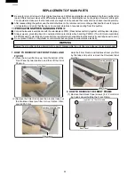
Page 24: ...eptible to static electricity and require extra care Do not place PWB K on Styrofoam or mirror mats that are prone to collect static electricity WARNING Unplug the air purifier before attempting to repair or disassemble the unit there is a danger of electrical shock 1 HOW TO REMOVE THE FRONT PANEL AND FILTER 1 Place the air purifier face up hold the bottom of the Front Panel by two locations and t...

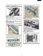
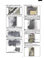
Page 25: ...ding head screws and two hooks of the Operation PWB from the Operation Switch Box and then separate the Operation PWB and Operation Button Operation PWB Operation PWB Operation Operation Switch witch Box ox symbol 3 x 8 mm screws symbol 3 x 8 mm screws Operation PWB Operation Switch Box symbol 3 x 8 mm screws Operation Operation Button utton Operation Button 3 Remove the 2 screws 3 x 12 mm binding...

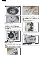
Page 26: ...ischarge Discharge Vent ent Discharge Vent 3 Remove the Discharge Guard from the Discharge Vent Discharge Discharge Vent ent Discharge Discharge Guard uard Discharge Vent Discharge Guard ASSEMBLY PRECAUTIONS Assemble so that the edge of the Discharge Guard faces upward as shown in the illustration above 6 HOW TO REMOVE THE PLASMACLUSTER UNIT 1 Disconnect the Cluster harness Remove the screw 4 x 10...

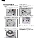
Page 27: ... Bottom hooks Push Control PWB Box Bottom 5 Remove the Control PWB Control PWB Box Top Control PWB Box Top Control Control PWB PWB Box Bottom Box Bottom Control PWB Control PWB Control PWB Box Top Control PWB Box Bottom Control PWB 8 HOW TO REMOVE THE POWER SUPPLY PWB 1 Remove the 2 screws 4 x 12 mm truss head screws holding the Power Supply Box component Power supply Power supply PWB Box Top PWB ...

Page 28: ...ion Motor Motor Back Rubber Cushion Front Rubber Cushion Motor ASSEMBLY PRECAUTIONS When installing the Motor set the Motor so that the circled flange holes line up with the positions on the Back Panel shown by the arrows Make sure the Motor Angle and Motor do not make contact Install so that the gaps Install so that the gaps are about the same are about the same Arrow mark Arrow mark Install so t...

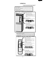
Page 29: ...omatically Manual Operation Regardless of the amount of impurities desired fan speed can be switched between Silent and Max POWER ON OFF button Used to start AUTO operation short beep and stop operation long beep Plasmacluster Indicator Light and Fan Speed Indicator Light AUTO turn on off Unless unplug the power cord the operation starts in the previous mode the unit was operated in AUTO Fan Speed...

Page 30: ... cleaning 3 CLEANING THE FAN AND INSIDE THE AIR PURIFIER Remove the 6 screws 4 x 10 mm truss head screws holding the intake guard and cluster maintenance cover CLEANING THE FAN Refer to P 24 of the Service Manual 4 How to remove the fan and remove the fan Wash the fan with water Use a towel to dry the washed fan or set it in a shady area with good ventilation to let it dry CLEANING INSIDE THE AIR ...

Page 31: ...llowing order place the sitting washer fan spring washer and nut on the motor shaft b Tighten the nut until the spring washer flattens out CAUTION Do not press down on the outer edge of the fan while tightening the nut 3 Install the intake guard with 4 screws 4 Place the filters into the filter frame and install the filter frame into the main unit Refer to P 26 5 Place the front panel 7 INSERT THE...

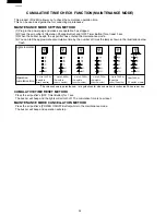
Page 32: ...n below flash Lights Indication 4H 1H 4H 1H 4H 1H 4H 1H 4H 1H 4H 1H Operation cumulative time The values shown in parentheses are guidelines for when operation is conducted 24 hours per day 0 hr to 1 440 hr 0 month to under 2 months 2 month to under 4 months 4 month to under 6 months 6 month to under 8 months 8 month to under 10 months 10 months or more Up to 2 880 hr Up to 4 320 hr Up to 5 760 hr...

Page 33: ... PC ABS 2 10 NFANSA004KKFZ FAN Acrylonitrile Butadiene Styrene V0 ABS 2 11 PBOX A012KKFZ CLUSTER BOX Polystyrene V0 HI PS 2 12 PCOV A067KKFZ POWER PWB BOX TOP Polycarbonate Acrylonitrile Butadiene Styrene V0 PC ABS 2 13 PCOV A068KKFZ POWER PWB BOX BOTTOM Polycarbonate Acrylonitrile Butadiene Styrene V0 PC ABS 2 14 PCOV A069KKFZ INSPECTION COVER Polystyrene V0 HI PS 2 15 PCOV A070KKFZ LSI PWB BOX T...

Page 34: ...L 2 20 HPNL A062KKTA Front panel base 1 BB 2 21 HPNL A107KKRA Ornament panel L 1 AZ 2 22 HPNL A063KKLA Ornament panel S 1 AQ 2 23 HBDG A002KKEA Al badge 1 AE 2 24 MROD A002KKWZ Front panel angle 1 AF 2 25 PFIL A074KKEZ Collect dust filter 1 AZ 2 26 PFIL A075KKEZ Deodorant filter 1 AY 2 27 PFIL A076KKEZ Pre filter 1 AS 2 28 PCUS A041KKEZ Filter cushion L 2 AC 2 29 PCUS A042KKEZ Filter cushion S 2 A...

Page 35: ...EWS 4 1 PPLT A016KKWZ Fan washer 1 AC 4 2 XNFS760 50000 Nut 1 4 3 XWSS760 10000 Spring washer 1 A XZBS730P08000 Tapping screw 4 B XZBSD30P10000 Screw special 2 AA C XZBS730P12000 Special tap screw 8 D XZBS740P08000 Tapping screw 3 E XBTS740P10000 Tapping screw 6 F XZTS740P10000 Special tap screw 3 G XZTS740P12000 Special tap screw 4 H XZBS740P12000 Tapping screw 10 I XZBS740P14000 Tapping screw 4 ...

Page 36: ... 3 3 5 3 2 3 1 4 1 4 2 4 3 2 2 2 3 2 6 2 8 2 4 2 5 1 2 2 9 2 10 2 11 2 41 2 12 2 14 2 13 2 19 2 20 2 28 2 38 2 40 2 37 2 37 2 29 2 30 2 31 2 32 2 34 2 35 2 33 2 33 2 36 2 36 2 25 2 26 2 27 2 21 2 22 2 23 2 17 2 18 2 15 2 16 1 4 1 5 1 5 1 5 1 5 1 3 2 7 Attached parts A C C H H J C G D D H E E E G C B F F I I K H ...

Reviews: