15
FU-28H-S
ELECTRIC CIRCUIT
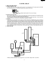
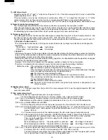
1. ABOUT LEAD-FREE SOLDER
1) Employing lead-free solder
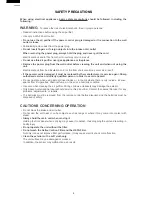
The "Main PWB" of this model employs lead-free solder. This is indicated by the "LF" symbol printed on the PWB
and in the service manual. The suffix letter indicates the alloy type of the solder.
Example:
L
F a
Sn-Ag-Cu
Indicates lead-free solder of tin, silver and copper.
2) Using lead-free wire solder
When repairing a PWB with the "LF" symbol, only lead-free solder should be used. (Using normal tin/lead alloy solder
may result in cold soldered joints and damage to printed patterns.)
As the melting point of lead-free solder is approximately 40ºC higher than tin/lead alloy solder, it is recommend that
a dedicated bit is used, and that the iron temperature is adjusted accordingly.
3) Soldering
As the melting point of lead-free solder (Sn-Ag-Cu) is higher and has poorer wettability, (flow), to prevent damage
to the land of the PWB, extreme care should be taken not to leave the bit in contact with the PWB for an extended
period of time. Remove the bit as soon as a good flow is achieved. The high content of tin in lead free solder will cause
premature corrosion of the bit. To reduce wear on the bit, reduce the temperature or turn off the iron when it is not
required. Leaving different types of solder on the bit will cause contamination of the different alloys, which will alter
their characteristics, making good soldering more difficult. It will be necessary to clean and replace bits more often
when using lead-free solder. To reduce bit wear, care should be taken to clean the bit thoroughly after each use.
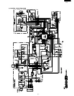
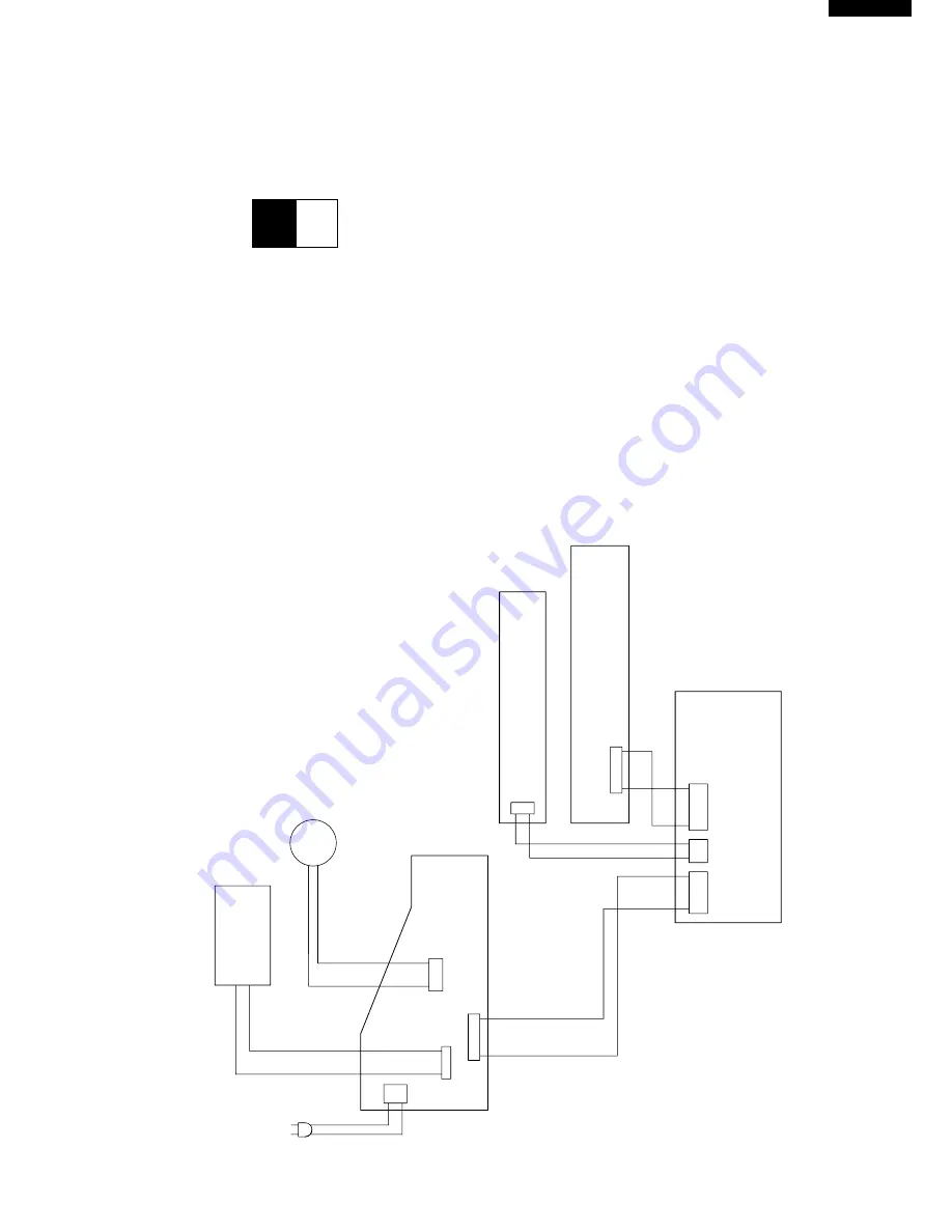
2. WIRING DIAGRAM
(CACCJA031KKEZ)
AC220-240V
(FW-VZA056KKEZ)
(CKITTA020AKKZ)
(CMOT-A021KKEZ)
CLUSTER HARNESS
UNIT
PLASMACLUSTER
POWER SUPPLY
PWB ASS'Y
POWER SUPPLY CORD
AC
AC
10P
WH-A
PC1
FM
MOTOR
FAN
CONTROL PWB ASS'Y
PWB ASS'Y
DISPLAY
SWITCH
PWB ASS'Y
WH-B
WH-C
6P
12P
CN-A
CN-B
10P
1
2P
CN-C
6P
PWB ass'y(CPWB-A056KKKZ)= Power supply PWB + Control PWB + Display PWB + Switch PWB


