1-7-1
TESTMODE
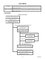
TEST MODE
Test Mode
ROM Renewal Mode
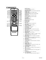
A power source is put, and [1], [2], [3], [4], and [ON SCREEN] buttons on the remote
control unit are pushed in that order while the tray is opening or after the “NO DISC”
display at the same time.
A power source is put, and [9], [8], [7], [6], and [DIRECT SKIP] buttons on the remote
control unit are pushed in that order while the tray is opening or after the “NO DISC”
display at the same time.
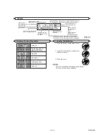
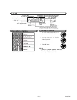
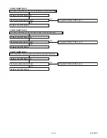
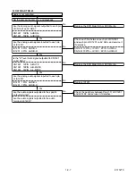
[TEST MODE]
Test Mode Flow Chart
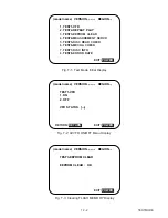
Test Mode Initial Display (Fig.T-1)
Displaying F/W Ver.
Displaying VFD F/W Ver.
< Press 1 button on the remote control unit. >
< Press 1 button on the remote control unit. >
< Press 2 button on the remote control unit. >
< Press 3 button on the remote control unit. >
< Press RETURN button on
the remote control unit. >
Returning to Test Mode Initial Display
All VFD ON/OFF
Menu Display (Fig. T-2)
Cearing FLASH MEMORY (Fig. T-3)
All VFD ON
All VFD OFF
Displaying VFD "TEST1"
Displaying VFD "TEST3"
Summary of Contents for DV-SL10H
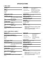
Page 2: ...1 1 1 E5752SP SPECIFICATIONS DV SL10H DV SL10S Y DV SL10S R ...
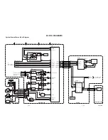
Page 33: ...DVD Main 1 3 Schematic Diagram 1 10 3 1 10 4 E5752SCD1 ...
Page 34: ...DVD Main 2 3 Schematic Diagram 1 10 5 1 10 6 E5752SCD2 ...
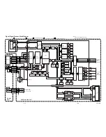
Page 38: ...AV 2 3 Schematic Diagram 1 10 13 1 10 14 E5752SCAV2 ...
Page 40: ...1 10 17 1 10 18 DVD Main CBA Top View BE5700G04012 ...
Page 41: ...1 10 19 1 10 20 DVD Main CBA Bottom View BE5700G04012 ...
Page 44: ...Function CBA Top View Function CBA Bottom View BE5714F01014 1 10 25 1 10 26 ...
Page 51: ...1 16 2 E5752EX Packing X10 X2 X4 S2 S2 S4 Unit S1 S5 X1 X17 DV SL10H only A22 A30 ...

