1-7-4
TESTMODE
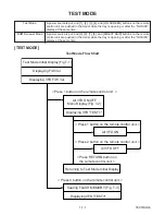
[ ERROR RATE MEASUREMENT]
1. Turn on the power to the player, remove the disk
from the tray, and close the tray.
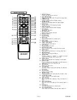
2. To put the DVD player into test mode, press [1], [2],
[3], [4], and [ON SCREEN] buttons on the remote
control unit in that order.
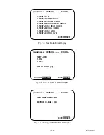
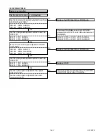
The unit will switch to Test Mode and Fig. a will be
displayed. For VFD, the current F/W version will be
displayed. (Fig. b)
(model name) VERSION
REGION
1. TEST1-VFD
2. TEST2-REPEAT PLAY
3.
TEST3-
EEPROM CLEAR
4.
TEST4-
MEASUREMENT SERVO
5.
TEST5-
DISC READ CHECK
6.
TEST6-
MECHA CHECK
7.
TEST7-
DISC INFO
8.
TEST8-
ERROR RATE
EXIT:
.
POWER
Fig. a Test Mode Screen
Fig. b Sample VFD in Test Mode
3. Press the [8] button to select "8. TEST 8 - ERROR
RATE." The on-screen display will change to the
screen shown in Fig. c. The VDF display will change
to the display shown in Fig. d.
(model name) VERSION
REGION
TEST8-ERROR RATE
DISC:DVD-V / DUAL LAYER / OPPOSITE
STA:
STATUS:
CHECK : OK
NOW MEASURE : L
RETURN:
.
EXIT:
POWER
RETURN
1
5
H
/
2
H
H
/
3
H
/
4
H
PO1st
00000 00000 00000 00000 00000
00000 00000 00000 00000 00000
Correct
Uncorrect
PI1st
PO2nd
PO3rd
PI2nd
(I) With a DVD inserted.
(model name) VERSION
REGION
TEST8-ERROR RATE
DISC: CD
STA:
STATUS:
CHECK : OK
NOW MEASURE :
RETURN:
.
EXIT:
POWER
RETURN
5
H
TRK
:
:
00000
00000
C1 Correct
C2 Uncorrect
:
:
(II) With a CD/VCD inserted.
Fig. c TEST8-ERROR RATE MODE
Fig. d Sample VFD in TEST8-ERROR RATE MODE
4. Put disk to be checked into the tray. Close the tray
using either the [OPEN/CLOSE] or [PLAY] button on
the unit or on the remote. The disk will automatically
be distinguished and error rate measurement will
begin.
Fig. c will display:
1
Inserted disk’s inner parameter (For DVD, Layer
0, initial address)
2
Inserted disk’s outer parameter (For DVD, Layer
0, final address)
3
Inserted disk’s Layer 1, initial address.
4
Inserted disk’s Layer 1, final address.
Depending on the contents of the inserted disk, 3
and 4 above may not be displayed.
Once the error rate measurement has started, if the
largest value resulting from the first three measure-
ments has a value of 2000 or less, and all values in
the "Uncorrect" row are 0, the message "CHECK :
OK" will be displayed on area
5
.
If the largest value is greater than 2000, the mes-
sage "CHECK : NG" will be displayed on area
5
.
The message "OK" or "NG" will continue to be
displayed without change until the measurement is
stopped. The error rate measurement will continue
to be updated.
5. "Correct" and "Uncorrect" in Fig. c:
(1) For DVDs the following will be displayed:
PO1st-Correct count; PO1st-Uncorrect count;
PI1st-Correct count; PI1st-Uncorrect count;
PO2nd-Correct; PO2nd-Uncorrect count;
PI2nd-Correct count; PI2nd-Uncorrect count;
PO3rd-Correct count; PO3rd-Uncorrect count.
The above ten numerical values will be displayed for
each 80 ECC block.
(2) For CD/VCDs the following will be displayed:
C1-Correct count; C2-Uncorrect count.
The values for these two items will be displayed
every 7350x4 frames.
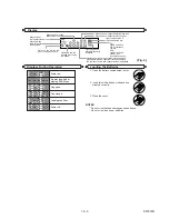
For VFD, the following will be displayed:
PO1st-Correct count; (C1-Correct count for CDs).
(Fig. e)
Fig. e: Sample VFD display of ERROR RATE
measurement
6. To end the ERROR RATE measurement, press the
[OPEN/CLOSE] button on either the unit or the
remote. After the display has ceased, press the
[POWER] button on either the unit or the remote to
shut off the power.
Summary of Contents for DV-SL10H
Page 2: ...1 1 1 E5752SP SPECIFICATIONS DV SL10H DV SL10S Y DV SL10S R ...
Page 33: ...DVD Main 1 3 Schematic Diagram 1 10 3 1 10 4 E5752SCD1 ...
Page 34: ...DVD Main 2 3 Schematic Diagram 1 10 5 1 10 6 E5752SCD2 ...
Page 38: ...AV 2 3 Schematic Diagram 1 10 13 1 10 14 E5752SCAV2 ...
Page 40: ...1 10 17 1 10 18 DVD Main CBA Top View BE5700G04012 ...
Page 41: ...1 10 19 1 10 20 DVD Main CBA Bottom View BE5700G04012 ...
Page 44: ...Function CBA Top View Function CBA Bottom View BE5714F01014 1 10 25 1 10 26 ...
Page 51: ...1 16 2 E5752EX Packing X10 X2 X4 S2 S2 S4 Unit S1 S5 X1 X17 DV SL10H only A22 A30 ...

