1-11-9
H9740FIS
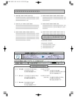
Note:
The following symbols will appear on the indicator panel to indicate the current mode or operation of the VCR.
On-screen modes will also be momentarily displayed on the tv screen when you press the operation buttons.
FUNCTION INDICATOR SYMBOLS
TV screen
Note:
OSD for mechanical error will be displayed for 5 sec. after the mechanical error occurs.
MODE
INDICATOR ACTIVE
When the drum is not working properly
When cassette loading mechanism is not
functioning correctly
When tape loading mechanism is not
functioning correctly
When reel and capstan mechanism is not
functioning correctly
"
A
P" is displayed on a TV screen. (Refer to Fig. 5.)
"
A
D" is displayed on a TV screen. (Refer to Fig. 4.)
"
A
C" is displayed on a TV screen. (Refer to Fig. 3.)
"
A
T" is displayed on a TV screen. (Refer to Fig. 2.)
"
A
R" is displayed on a TV screen. (Refer to Fig. 1.)
P-ON Power safety detection
When reel and capstan mechanism is not functioning
correctly
A
R
Fig. 1
When tape loading mechanism is not functioning
correctly
A
T
Fig. 2
When cassette loading mechanism is not functioning
correctly
A
C
Fig. 3
When the drum is not working properly
Fig. 4
A
D
P-ON Power safety detection
A
P
Fig. 5
Summary of Contents for DV-NC100S
Page 48: ...1 12 3 1 12 4 H9740SCM1 Main 1 9 Schematic Diagram VCR Section ...
Page 50: ...Main 3 9 Schematic Diagram VCR Section 1 12 7 1 12 8 H9740SCM3 ...
Page 51: ...Main 4 9 Schematic Diagram VCR Section 1 12 9 1 12 10 H9740SCM4 ...
Page 52: ...1 12 11 1 12 12 H9740SCM5 Main 5 9 Schematic Diagram VCR Section ...
Page 53: ...Main 6 9 Schematic Diagram VCR Section 1 12 13 1 12 14 H9740SCM6 ...
Page 54: ...Main 7 9 DVD Open Close Schematic Diagrams VCR Section 1 12 15 1 12 16 H9740SCM7 ...
Page 55: ...Main 8 9 Schematic Diagram VCR Section 1 12 17 1 12 18 H9740SCM8 ...
Page 56: ...1 12 19 1 12 20 H9740SCM9 Main 9 9 Schematic Diagram VCR Section ...
Page 58: ...Jack A Schematic Diagram 1 12 23 1 12 24 H9740SCJ ...
Page 59: ...AFV Schematic Diagram 1 12 25 1 12 26 H9740SCAFV ...
Page 60: ...1 12 27 1 12 28 H9740SCD1 DVD Main 1 3 Schematic Diagram DVD Section ...
Page 61: ...1 12 29 1 12 30 H9740SCD2 DVD Main 2 3 Schematic Diagram DVD Section ...
Page 69: ...1 12 46 BE5900G04012 1 12 45 DVD MAIN CBA Top View ...
Page 70: ...1 12 47 1 12 48 BE5900G04012 DVD MAIN CBA Bottom View ...