43
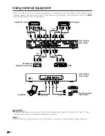
Using external equipment
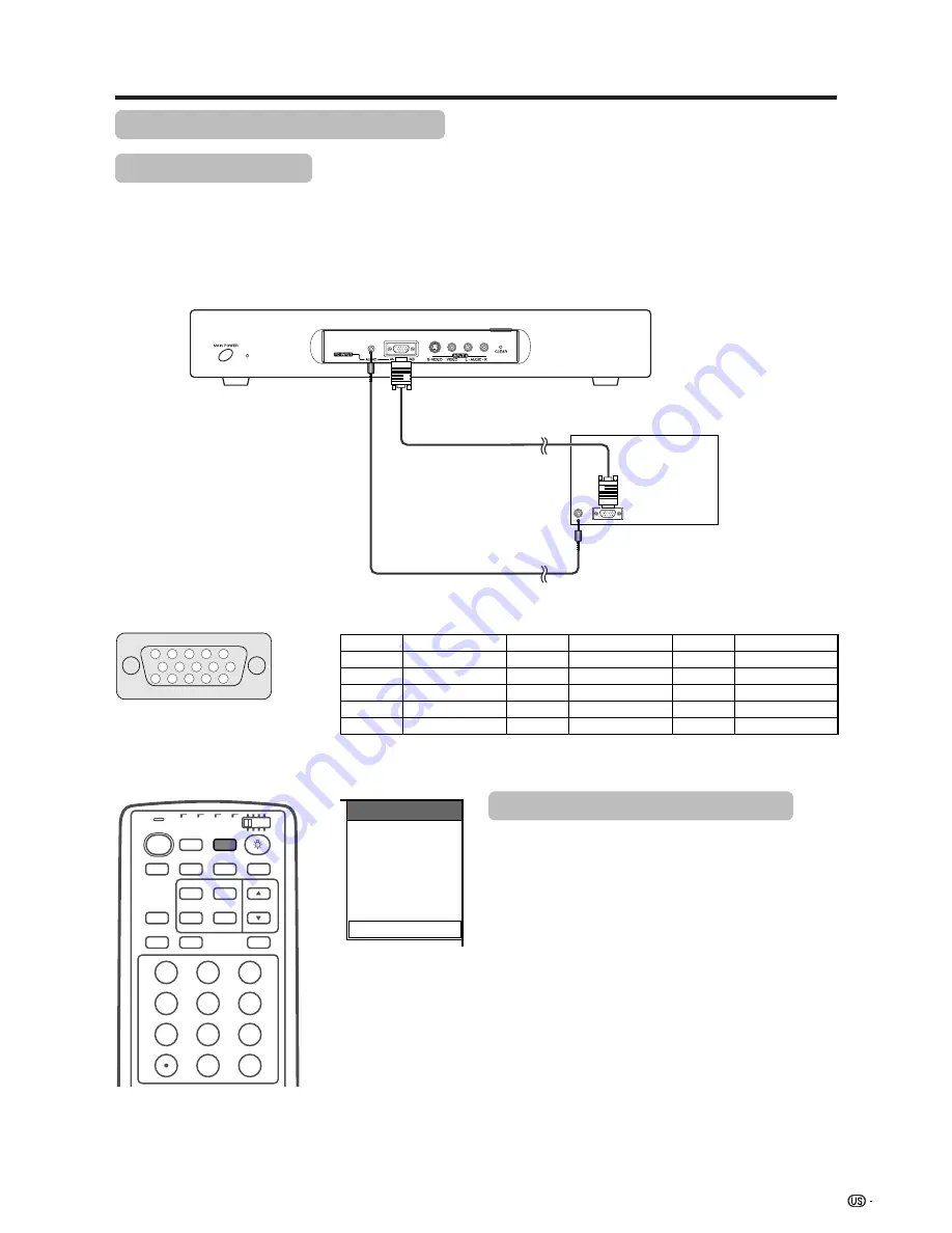
RGB cable
(commercially available)
AVC System (front view)
ø 3.5 mm stereo minijack cable
(commercially available)
Computer
15
14
13
12
9
11
10
8
7
6
5
4
3
2
1
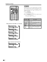
INPUT SOURCE
TV
INPUT1
INPUT2
INPUT3
INPUT4
PC
Pin No.
Signal name
Pin No.
Signal name
Pin No.
Signal name
1
R
6
GND (Ground)
q
Not connected
2
G
7
GND (Ground)
w
SDA
3
B
8
GND (Ground)
e
HD
4
Not connected
9
Ⳮ
5V
r
VD
5
CSYNC
0
GND (Ground)
t
SCL
Viewing an image from a computer
Connecting a computer
Use the PC terminals to connect a computer.
A
• The PC input terminals are DDC1/2B-compatible.
• Refer to page 71 for a list of computer signals compatible with the System.
Signal names for 15-pin mini D-sub connecter
A
• Macintosh adaptor may be required for use for some Macintosh computers.
Displaying an image from a computer
When connecting to a computer, the correct input
signal type is automatically detected. If the computer
image does not come in clearly, you may need to set
the Auto Sync. adjustment on the “Auto Sync.” in the
menu. (See page 46.)
You only need to select the input source on the “INPUT
SOURCE” menu.
To view an image from a computer, select “PC” from
the “INPUT SOURCE” menu using
INPUT
on the
remote control unit or on the Dispaly. (See page 47.)
A
• Each time
INPUT
is pressed, the input source toggles.
• PC INPUT terminals cannot be used for audiovisual
equipment. Use the INPUT 3 (HD) terminal on the rear
of the AVC System when connecting audiovisual
equipment with an RGB signal. (See page 41.)
INPUT
TV
ANT-A/B
SURROUND
FRONT
TWIN
MODE
AV
POWER
MTS
CC
PICTURE
SELECT
SUB
TWIN CH
FREEZE
MODE
VIEW
SLEEP
LEARN
EDIT/
ENT
DISPLAY
INPUT
TV
VCR
CBL
/SAT
/DTV
DVD
/LD
1
2
3
4
5
6
7
8
9
100
0


