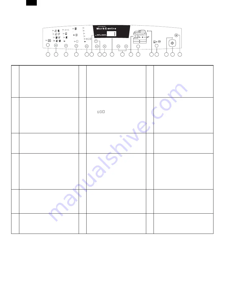
background image

2. Control Panel

The control panel has keys and lights that are used to control and display the conditions of the WorkCentre.

1

Book Mode (XD104/124f only): Select
book mode when you want to make
copies from a bound document.

2

1-Sided/2-Sided Mode (XD155df only):
Use the 2-Sided copy feature to make
one or two-sided copies from one or
two-sided originals. Refer to the
Making Copies on the Automatic
Document Feeder section for detailed
information.

3

Image Quality Mode: The image quality
mode is used to maximize copy quality.
Auto- for originals with a colored
background or mixed text and graphics.
Text - for originals that contain mainly text.
Photo - for copying photographs.
Toner Save - decreases the overall
copy density.

4

Copy Contrast: Press the contrast keys
to lighten or darken copies while in the
Text, Photo, or Toner Save settings.
Refer to the Image Quality section for
detailed information.

5

Preset Reduction/Enlargement: Press
this key to select any of the preset
reductions or enlargements.

6

Percentage Indicator: The indicator will
light when any reduction or
enlargement setting is selected.

The   (customer 

settable)

percentage has been set at the
factory for 50%. Refer to
Customizing Your WorkCentre for
information about changing this
percentage.

7

Variable Percentage: Press the down
key to decrease the percentage. Press
the up key to increase the percentage.
Any percentage from 50% to 200%
may be selected.

8

%: Press this key to display the
reduction/enlargement percentage
selected.

9

Display Window: Copy quantity,
reduction/enlargement settings, and
status codes appear in this area.

10

Quantity Keys: Select up to 100
copies. Press the 1 key to increase
the quantity by one. Press the 10 key
to increase the quantity by 10.

11

WorkCentre Diagram: Helps you locate
areas that require your attention. The
indicators will flash in the area
requiring attention. For additional
information refer to the Problem
Solving section.

12

Paper Supply Selection
(XD104/105f/120f/124f/155df only):
Press to change the selected paper
supply. The selected paper supply
location will be indicated by a green
light on the WorkCentre diagram.

To display the number of copies
requested during the copy run press
the 10 key.

Press the Clear key to clear the
selected quantity.

13

SPF/ADF Misfeed Indicator: This
indicator will light when a misfeed
occurs in the SPF or the ADF.

14

On-line/Off-line Key: Press this button
to alternate between On-line and Off-
line status. When the light is lit, the
printer is On-line.

15

Ready Indicator: When the light is ON
(not flashing), the WorkCentre is ready
to make copies. When the light is
flashing after the Start key is pressed,
the WorkCentre is warming up and the
copy cycle will begin automatically.

16

Start: Press this key to begin copying.

17

Clear/Stop: Press this key to stop the
WorkCentre while making copies or to
clear copy quantity. If the key is
pressed twice quickly, all programming
will be cleared.

The display will change to 1 and
increases by 1 as each copy is
made.

78%

Auto

86%

10 0%

129%

200% Max

10

1

C

1

3

4

5

6

7

8

10

14

16

17

15

9

2

13

11

12

AL-1550

3 – 2

Summary of Contents for AL-1550

Page 1: ...ON 4 1 5 OPERATIONAL DESCRIPTIONS 5 1 6 DISASSEMBLY AND ASSEMBLY 6 1 7 ADJUSTMENTS 7 1 8 SIMULATION TROUBLE CODES 8 1 9 USER PROGRAMS 9 1 10 ELECTRICAL SECTION 10 1 11 CIRCUIT DIAGRAM 11 1 PARTS GUIDE CONTENTS Parts marked with is important for maintaining the safety of the set Be sure to replace these parts with specified ones for maintaining the safety and performance of the set This document ha...

Page 2: ... environmental conditions and the input volt age 3 Copy performance Section item Details Copy speed First copy time Tray paper feed 9 6sec Pre heat mode 16sec or delow Auto power shut off mode 23sec or delow Feed from Tray1 Scan Once Print Many Mode 13 sec Manual paper feed Single 10 0sec Multi 8 0sec Pre heat mode 16sec R SPF Tray1 13 5sec Copy speed OC AB system A4 Landscape Same size 15 Enlarge...

Page 3: ...or less Reduction 50 6 0mm or less Trailing edge Same size 1st Page 5 0mm 1 0 2nd Page 5 0mm or less Enlarge 200 1st Page 2 5mm 1 0 2nd Page 2 5mm or less Reduction 50 1st Page 10 0mm 1 0 2nd Page 10 0mm or less Void area R SPF Duplex Ieading edge 1 4mm Trailing edge 1st Page 5mm 1 0 2nd Page 5mm or less Side edge void area 3mm or less per side Image loss R SPF Duplex Ieading edge Same size 4 0mm ...

Page 4: ...per tray bypass paper guides 9 Alternate paper tray 10 Paper guides 11 Release latch 12 Front cover 13 Paper tray 1 14 Paper tray 2 15 Exit tray 16 Lift area 17 Power switch 18 Power connection 19 Parallel port 20 Serial number 1 XD104 105f 124f 155df only 2 XD120f 124f 155df only 3 4 5 SPF XD103f 105f 120f ADF XD155df only 1 15 13 14 12 6 2 8 10 9 7 11 15 16 17 19 18 20 AL 1550 3 1 ...

Page 5: ...y the reduction enlargement percentage selected 9 Display Window Copy quantity reduction enlargement settings and status codes appear in this area 10 Quantity Keys Select up to 100 copies Press the 1 key to increase the quantity by one Press the 10 key to increase the quantity by 10 11 WorkCentre Diagram Helps you locate areas that require your attention The indicators will flash in the area requi...

Page 6: ...cure the paper tray button and the shipping screw in the locations shown Turn the paper tray button to secure its storage position Note Save the paper tray button and the shipping screw They will be needed if the WorkCentre has to be moved 7 Load paper into the tray Refer to the Loading Paper section for additional information Do not fill above the max line 8 Push the paper tray firmly back into t...

Page 7: ...tion Note The procedures for loading paper into tray 1 and tray 2 are identical 3 Adjust the paper guides to the desired paper size Squeeze the side guide Lift and insert the rear guide When adding paper larger than 8 5L11 A4 remove the rear guide and store it in the pocket in front of the side guide 4 Fan the paper and insert it into the tray Ensure that the paper corners are under the corner snu...

Page 8: ...s exposed It is sent to the document exit section by the transport roller and the paper exit roller R SPF gate solenoid ON The document is sent to the intermediate tray but not dis charged completely It is stopped once and switchback operation is performed It is sent through the PS roller and the ex posure section without exposure operation to the document exit section R SPF gate solenoid OFF The ...

Page 9: ...r is displayed 2 Enter the code number and press the START key and the setting will be changed 5 Fusing temperature setting in duplex copying Operation Procedure 1 When this simulation is executed the currently set code number is displayed 2 Enter the code number corresponding to the duplex and press the START key The setting is changed accordingly The above shift temperature set by this simulatio...

Page 10: ...tion is at the rear edge section and use this simulation so that the lead edge of the print image is fitted Printing is started at the print start position in the direction from the bottom to the top of image data stored in the memory When the simulation set value is entered the scanning end position and resultantly the bottom data position stored in the memory are changed to adjust the image lead...

Page 11: ...m 60 sec to 90 sec 1 Press the right and the left exposure adjustment keys simul taneously to start setting Keep pressing the keys for five sec Display lamps blink simultaneously and is displayed on the copy quantity display 2 Select the function code with the 10 digit key copy quantity set key The number of the selected function blinks on the digit of 10 on the copy quantity display For auto clea...

Page 12: ... 10 ELECTRICAL SECTION 1 Block diagram A Overall block diagram AL 1550 10 1 ...

Page 13: ...B Main PWB block diagram AL 1550 10 2 ...

Page 14: ...ignal table The additional signal is as follows Pin No Signal name In Out Connection Descriptions 201 SGS Output TR array IC SPF gate solenoid control signal H Gate solenoid ON R SPF only 202 SRRC Output TR array IC SPF resist roller clutch control signal H Clutch ON R SPF only 203 SPUS Output TR array IC SPF pickup solenoid control signal H Solenoid ON 208 SPFS Output TR array IC SPF paper feed s...

Page 15: ...a current flows through the mirror motor 5 Duplex motor circuit The duplex motor is a stepping motor Its driver is IC111 darlington sink transistor driver IC TD62064AP For control the CPU outputs a drive signal to IC111 to drive the duplex motor by 1 2 phase excitement M 24V 24V mir RY102 G5V 2 OMRON RY101 G5V 2 OMRON M ULN2003 SMSEL SPF motor 1 C4 DMT0 1 C4 DMT1 1 C4 DMT2 1 C4 DMT3 R286 2 2KJ 3 R...

Page 16: ... 11 CIRCUIT DIAGRAM MCU 1 AL 1550 11 1 ...

Page 17: ...MCU 2 AL 1550 11 2 ...

Page 18: ...MCU 3 AL 1550 11 3 ...

Page 19: ...MCU 4 AL 1550 11 4 ...

Page 20: ...MCU 5 AL 1550 11 5 ...

Page 21: ...MCU 6 AL 1550 11 6 ...

Page 22: ...MCU 7 AL 1550 11 7 ...

Page 23: ...OPU AL 1550 11 8 ...

Page 24: ...ACTUAL WIRING DIAGRAM 1 AL 1550 11 9 ...

Page 25: ...ACTUAL WIRING DIAGRAM 2 DSPF UNIT AL 1550 11 10 ...

Page 26: ...a retrieval system or transmitted in any form or by any means electronic mechanical photocopying recording or otherwise without prior written permission of the publisher SHARP CORPORATION Printing Reprographic Systems Group Quality Reliability Control Center Yamatokoriyama Nara 639 1186 Japan 1999 March Printed in Japan N AL 1550 ...

Reviews: