Sharp AL-1550 Service Manual Download Page 11

[9] USER PROGRAM

The conditions of factory setting can be changed according to the use conditions.

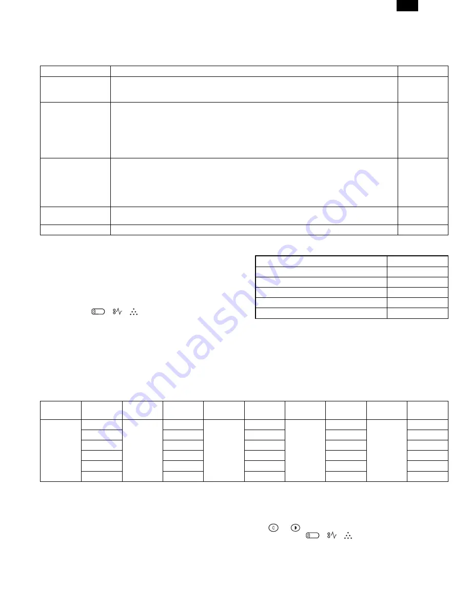
1. Functions which can be set with the user program

Function

Contents

Factory setting

Auto clear.

When a certain time is passed after completion of copying, this function returns to the initial state
automatically. The time to reach the initial state can be set in the range of 10 sec to 120 sec. This
function can be disabled.

60 sec

Pre-heat.

When the copier is left unused with the power ON, the power consumption is automatically reduced
to about 40Wh/H (

 Note).

The time to start this function can be set in the range of 30 sec to 90 sec by the unit of 30 sec.
This function cannot be disabled.

90 sec

When this function is operated, the pre-heat lamp on the operation panel lights up.
To return to the initial state, press any key on the operation panel. (When the COPY button is
pressed, a copy is made after returning to the initial state.)

Auto shut off
passing time.

When the copier is left unused with the power ON, the power consumption is automatically reduced
to about 18Wh/H (

 Note). The time to start this function can be set in the range of 2 min to 120

min.

5 min

When this function is operated, all the lamps except for the pre-heat lamp on the operation panel
turn off.
To return to the initial state, press the COPY button.

Stream feeding.

After completion of copying with the automatic document feeder (SPF), when documents are set
while the SPF indicator is blinking (for about 5 sec), the documents are automatically fed.

Set

Auto shut off setting

Used to set or cancel this function.

Set

Note: The power consumption values in pre-heat and auto shut off may be varied depending on the use conditions.

2. Change the setting.

Example: Changing the time to operate the auto shut off function

(Change from 60 sec to 90 sec)

1) Press the right and the left exposure adjustment keys simul-

taneously to start setting.

Keep pressing the keys for five sec.

Display lamps (      ,      ,    ) blink simultaneously and “- -” is
displayed on the copy quantity display.

2) Select the function code with the 10-digit key (copy quantity

set key).

The number of the selected function blinks on the digit of 10 on the
copy quantity display.

For auto clear, select “1.”

For setting, refer to the following function codes.

Function name

Function code

Auto clear

1

Pre-heat

2

Auto shut off passing time

3

Stream feeding

4

Auto shut off setting

5

[Cancel] If a wrong code is entered, press the clear key and enter the

correct function code.

3) Press the COPY button.

The number blinking on the digit of 10 of the coyp quantity display
is lighted.

The number of the current set code blinks on the digit of 1.

4) Select the setting code with 1-digit key (copy quantity set key).

To set to 90 sec, select “3.”

For setting, refer to the following set codes.

Function
name

Set code

Function
name

Set code

Function
name

Set code

Function
name

Set code

Function
name

Set code

Auto clear

0 (Cancel)

Pre-heat

0 (30 sec)

Auto shut
off

0 (2 min)

Stream
feeding

0 (Cancel)

Auto shut
off setting

0 (Cancel)

1 (30 sec)

1 (60 sec)

1 (5 min) 

1 (Setting) 

1 (Setting) 

2 (60 sec) 

2 (90 sec)

2 (15 min)

3 (90 sec)

3 (30 min)

4 (120 sec)

4 (60 min)

5 (10 sec)

5 (120 min)

 : Factory setting

The number of the selected set code blinks on the digit of 1 of the
copy quantity display.

[Cancel] When a wrong number of the function code is set, press the

clear key and perform the procedure again from 2.

5) Press the COPY button.

The number blinking on the digit of 1 of the copy quantity display is
lighted up. This means the setting is completed.

[Note] To set another function, press the clear key after completion of

this operation and perform the procedure from 2.

6) Press either one of exposure adjustment keys 

(     or     ) to complete the setting.

Display 

lamps 

(   , 

  ,  ) 

go 

off 

and 

the 

copy 

quantity 

dis-

play returns to the normal state.

AL-1550

9 – 1

Summary of Contents for AL-1550

Page 1: ...ON 4 1 5 OPERATIONAL DESCRIPTIONS 5 1 6 DISASSEMBLY AND ASSEMBLY 6 1 7 ADJUSTMENTS 7 1 8 SIMULATION TROUBLE CODES 8 1 9 USER PROGRAMS 9 1 10 ELECTRICAL SECTION 10 1 11 CIRCUIT DIAGRAM 11 1 PARTS GUIDE CONTENTS Parts marked with is important for maintaining the safety of the set Be sure to replace these parts with specified ones for maintaining the safety and performance of the set This document ha...

Page 2: ... environmental conditions and the input volt age 3 Copy performance Section item Details Copy speed First copy time Tray paper feed 9 6sec Pre heat mode 16sec or delow Auto power shut off mode 23sec or delow Feed from Tray1 Scan Once Print Many Mode 13 sec Manual paper feed Single 10 0sec Multi 8 0sec Pre heat mode 16sec R SPF Tray1 13 5sec Copy speed OC AB system A4 Landscape Same size 15 Enlarge...

Page 3: ...or less Reduction 50 6 0mm or less Trailing edge Same size 1st Page 5 0mm 1 0 2nd Page 5 0mm or less Enlarge 200 1st Page 2 5mm 1 0 2nd Page 2 5mm or less Reduction 50 1st Page 10 0mm 1 0 2nd Page 10 0mm or less Void area R SPF Duplex Ieading edge 1 4mm Trailing edge 1st Page 5mm 1 0 2nd Page 5mm or less Side edge void area 3mm or less per side Image loss R SPF Duplex Ieading edge Same size 4 0mm ...

Page 4: ...per tray bypass paper guides 9 Alternate paper tray 10 Paper guides 11 Release latch 12 Front cover 13 Paper tray 1 14 Paper tray 2 15 Exit tray 16 Lift area 17 Power switch 18 Power connection 19 Parallel port 20 Serial number 1 XD104 105f 124f 155df only 2 XD120f 124f 155df only 3 4 5 SPF XD103f 105f 120f ADF XD155df only 1 15 13 14 12 6 2 8 10 9 7 11 15 16 17 19 18 20 AL 1550 3 1 ...

Page 5: ...y the reduction enlargement percentage selected 9 Display Window Copy quantity reduction enlargement settings and status codes appear in this area 10 Quantity Keys Select up to 100 copies Press the 1 key to increase the quantity by one Press the 10 key to increase the quantity by 10 11 WorkCentre Diagram Helps you locate areas that require your attention The indicators will flash in the area requi...

Page 6: ...cure the paper tray button and the shipping screw in the locations shown Turn the paper tray button to secure its storage position Note Save the paper tray button and the shipping screw They will be needed if the WorkCentre has to be moved 7 Load paper into the tray Refer to the Loading Paper section for additional information Do not fill above the max line 8 Push the paper tray firmly back into t...

Page 7: ...tion Note The procedures for loading paper into tray 1 and tray 2 are identical 3 Adjust the paper guides to the desired paper size Squeeze the side guide Lift and insert the rear guide When adding paper larger than 8 5L11 A4 remove the rear guide and store it in the pocket in front of the side guide 4 Fan the paper and insert it into the tray Ensure that the paper corners are under the corner snu...

Page 8: ...s exposed It is sent to the document exit section by the transport roller and the paper exit roller R SPF gate solenoid ON The document is sent to the intermediate tray but not dis charged completely It is stopped once and switchback operation is performed It is sent through the PS roller and the ex posure section without exposure operation to the document exit section R SPF gate solenoid OFF The ...

Page 9: ...r is displayed 2 Enter the code number and press the START key and the setting will be changed 5 Fusing temperature setting in duplex copying Operation Procedure 1 When this simulation is executed the currently set code number is displayed 2 Enter the code number corresponding to the duplex and press the START key The setting is changed accordingly The above shift temperature set by this simulatio...

Page 10: ...tion is at the rear edge section and use this simulation so that the lead edge of the print image is fitted Printing is started at the print start position in the direction from the bottom to the top of image data stored in the memory When the simulation set value is entered the scanning end position and resultantly the bottom data position stored in the memory are changed to adjust the image lead...

Page 11: ...m 60 sec to 90 sec 1 Press the right and the left exposure adjustment keys simul taneously to start setting Keep pressing the keys for five sec Display lamps blink simultaneously and is displayed on the copy quantity display 2 Select the function code with the 10 digit key copy quantity set key The number of the selected function blinks on the digit of 10 on the copy quantity display For auto clea...

Page 12: ... 10 ELECTRICAL SECTION 1 Block diagram A Overall block diagram AL 1550 10 1 ...

Page 13: ...B Main PWB block diagram AL 1550 10 2 ...

Page 14: ...ignal table The additional signal is as follows Pin No Signal name In Out Connection Descriptions 201 SGS Output TR array IC SPF gate solenoid control signal H Gate solenoid ON R SPF only 202 SRRC Output TR array IC SPF resist roller clutch control signal H Clutch ON R SPF only 203 SPUS Output TR array IC SPF pickup solenoid control signal H Solenoid ON 208 SPFS Output TR array IC SPF paper feed s...

Page 15: ...a current flows through the mirror motor 5 Duplex motor circuit The duplex motor is a stepping motor Its driver is IC111 darlington sink transistor driver IC TD62064AP For control the CPU outputs a drive signal to IC111 to drive the duplex motor by 1 2 phase excitement M 24V 24V mir RY102 G5V 2 OMRON RY101 G5V 2 OMRON M ULN2003 SMSEL SPF motor 1 C4 DMT0 1 C4 DMT1 1 C4 DMT2 1 C4 DMT3 R286 2 2KJ 3 R...

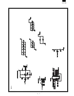
Page 16: ... 11 CIRCUIT DIAGRAM MCU 1 AL 1550 11 1 ...

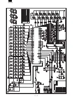
Page 17: ...MCU 2 AL 1550 11 2 ...

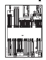
Page 18: ...MCU 3 AL 1550 11 3 ...

Page 19: ...MCU 4 AL 1550 11 4 ...

Page 20: ...MCU 5 AL 1550 11 5 ...

Page 21: ...MCU 6 AL 1550 11 6 ...

Page 22: ...MCU 7 AL 1550 11 7 ...

Page 23: ...OPU AL 1550 11 8 ...

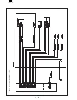
Page 24: ...ACTUAL WIRING DIAGRAM 1 AL 1550 11 9 ...

Page 25: ...ACTUAL WIRING DIAGRAM 2 DSPF UNIT AL 1550 11 10 ...

Page 26: ...a retrieval system or transmitted in any form or by any means electronic mechanical photocopying recording or otherwise without prior written permission of the publisher SHARP CORPORATION Printing Reprographic Systems Group Quality Reliability Control Center Yamatokoriyama Nara 639 1186 Japan 1999 March Printed in Japan N AL 1550 ...

Reviews: