GB-3
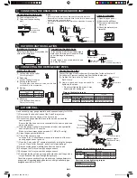
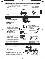
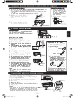
Flaring the pipe end
(1) Cutting with a pipe cutter
Cut at a right angle.
(2) Deburring
Allow no cuttings in the pipe.
(3) Putting in the
fl
are nut
For liquid pipe of the indoor unit side, use the
fl
are
nut included in the accessories.
(4) Flaring
Flare processing dimensions(A)
Tool
A
R410A tool
0 - 0.5 mm
Conventional tool 1.0 - 1.5 mm
(5) Checking
To
be
fl
ared perfectly circular.
Flare nut not missing
.
Not running wavy.
Not left in water.
6 CONNECTING THE REFRIGERANT PIPES
Flare nut
No trap
allowed.
Not to rise.
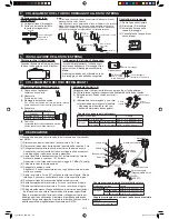
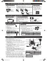
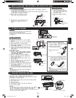
Connecting the drain hose
(1) Connect a drain hose.
(2) Tape over the connecting
part.
ø17 mm
Connecting the pipes
Connect the pipes for the indoor unit
fi
rst and then for the outdoor unit.
For indoor unit, remove sealing cap from the liquid pipe end.
(1) Tighten the flare nuts by hand for the
fi
rst 3-4 turns.
(2) Use a wrench and torque wrench to
tighten up the pipes.
• Do not over tighten the pipes. It may
be deformed or damaged.
4 CONNECTING THE DRAIN HOSE TO THE INDOOR UNIT
7 AIR REMOVAL
No trap allowed.
90°
A
Lo
Hi
Notes:
• Be sure to lay the drain hose downward for smooth drain
fl
ow.
• Be careful not to allow the drain hose to rise, form a trap or leave
its end in water, as shown below.
• Coil thermal insulation around a drain hose extension, if running in
the room.
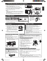
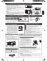
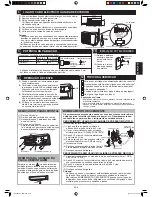
Use a vacuum pump, gauge manifold and hoses exclusively for R410A.
(1) Remove both valve shaft caps of the 2 and 3-way valves.
(2) Remove the service port cap of the 3-way valve.
(3) Connect the gauge manifold hose to the service port and the
vacuum pump.
Be sure that the hose end to be connected to the service port has a
valve core pusher.
(4) Open the gauge manifold low-pressure valve(Lo) and operate the
vacuum pump for 10-15 minutes.
Make sure the compound gauge reads -0.1 MPa(-76 cmHg).
(5) Close the gauge manifold valve.
(6) Turn off the vacuum pump.
Leave as it for 1-2 minutes and make sure the needle of the com-
pound gauge does not go back.
(7) Open the 2-way valve 90° counterclockwise by turning the hexagon
wrench. Close it after 5 second, and check for gas leakage.*
(8) Disconnect the gauge manifold hose from the service port.
(9) Fully open the 2-way valve with hexagon wrench.
(10) Fully open the 3-way valve with hexagon wrench.
(11) Firmly tighten the service port cap and both valve shaft caps with a
torque wrench at the speci
fi
ed tightening torque.
* Check the pipe connections for gas leak using a leakage detector or
soapy water. Regarding leakage detector, use high-sensitivity type
designed specially for R410A.
540
286
Gauge manifold
Compound gauge
Vacuum pump
Service port cap
3-way valve
Valve shaft cap
Valve shaft cap tightening torque
Pipe size
Torque
Liquid side 1/4"
24±3 N · m (2.4±0.3 kgf · m)
Gas side
3/8"
AE-A9NR
24±3 N · m (2.4±0.3 kgf · m)
1/2"
AE-A12NR
31±3 N · m (3.1±0.3 kgf · m)
Service port cap tightening torque
Torque
11±1 N · m (1.1±0.1 kgf · m)
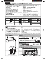
Installation dimension
Referring to the
fi
gure,
fi
rmly fasten the
outdoor unit with bolts.
5 OUTDOOR UNIT INSTALLATION
Checking drainage
(1) Open the open panel.
(2) Remove the air
fi
lters.
(3) Pour some water into the
drain pan.
(4) Check the water drains
smoothly.
Connecting the drain hose
In the heating mode, the unit discharged
water from its drain port. Connect a drain
hose if drainage is necessary.
Note:
In cold regions, do not use a drain hose
as it may be frozen.
Drain hose
(Commercially available)
Drain port
9
DRAIN HOSE
ADAPTER
Wrench
Torque wrench
2-way valve
Hexagon wrench
(Diagonally 5 mm)
OPEN
Service port
CLOSE
Flare nut tightening torque
Pipe size
Torque
Liquid side 1/4" (ø 6.35 mm)
16±2 N·m (1.6±0.2 kgf·m)
Gas side
AY-AP9NR
3/8" (ø 9.52 mm) 38±4 N·m (3.8±0.4 kgf·m)
AY-AP12NR
1/2" (ø 12.7 mm) 55 ± 5 N·m (5.5 ± 0.5 kgf·m)
Drain hose
(Commercially
available)
Bottom frame
04_A3AYAP9_2NR.indb GB-3
04_A3AYAP9_2NR.indb GB-3
2012-01-12 20:45:10
2012-01-12 20:45:10

