14U10/15
14U20/25
9
9-1
9-2
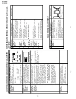
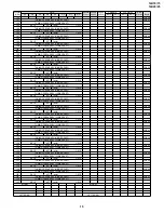
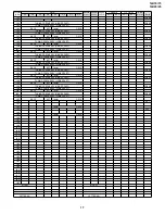
A/V INPUT AND OUTPUT CHECKING
(Continued)
No.
Adjusment point
Conditions/Adjusting pr
ocedure
W
a
vef
orm or other
s
SUBW
OOFER
OUTPUT
CHECK
1.
Receiv
e "P
AL Colour Bar" signal (Sound 400Hz,
100% Mod.)
2.
Set the sound output to 2.83
Vr
ms b
y
v
olume k
e
y.
3.
T
e
rm
inal the "Sub-W
oof
er" output with a 22 kilo-
ohms impedance
.
Mak
e
sure that output is 4.0Vp-p
±
3 dB
.
3
FUNCTION OPERA
TION CHECKING (VIDEO AND A
UDIO)
No.
Adjusment point
Conditions/Adjusting pr
ocedure
W
a
vef
orm or other
s
CONTRAST
key
1.
Receiv
e "Monoscope P
atter
n" signal.
2.
Set P-Mode to select CONTRAST
.
3.
Press
V
olume Up/Do
w
n k
e
y to chec
k whether the
CONTRAST eff
ect is OK or not.
1
1.
Receiv
e "Color Bar" signal.
2.
Set P-Mode to select COLOUR.
3.
Press
V
o
lume Up/Do
w
n k
e
y to chec
k whether
the COLOUR eff
ect is OK or not.
2
COLOUR ke
y
BRIGHTNESS
key
1.
Receiv
e "Monoscope P
atter
n" signal.
2.
Set P-Mode to select BRIGHTNESS.
3.
Press
V
o
lume Up/Do
w
n k
e
y to chec
k
whether
the BRIGHTNESS eff
ect is OK or not.
3
TINT ke
y
1.
Receiv
e the "NTSC Colour Bar" signal thr
u A
V
in.
2.
Set P-Mode to select
TINT
.
3.
Press
V
olume Up/Do
w
n k
e
y to chec
k
TINT
, UP
for GREEN direction and DOWN for PURPLE di-
rection whether is OK or not.
4
SHARPNESS
Key
1.
Receiv
e "Monoscope P
atter
n" signal.
2.
Set P-mode to select SHARPNESS.
3.
Press
V
olume Up/Do
wn k
e
y to chec
k whether the
SHARPNESS eff
ect is OK or not.
5
CH DISPLA
Y
COLOUR
1.
All Ch (1~99) will ha
v
e
an OSD displa
y of the
channel n
u
mber in g
reen colour under AFT ON
condition.
6
NORMAL K
e
y
7
1.
Once in PICTURE Mode
, and the NORMAL k
ey
is pressed, all the settings will be present to nor-
mal setting.
(Normal setting value for every mode).
»
CONTRAST
: MAX
»
COLOUR
: CENTER
»
BRIGHTNESS
: CENTER
»
TINT
: CENTER
»
SHARPNESS
: CENTER
No.
Adjusment point
Conditions/Adjusting pr
ocedure
W
a
vef
orm or other
s
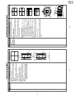
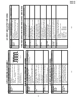
SUB-TINT (I
2
C
BUS CON-
TROL)
1
.
Receive the "NTSC3.58 Colour Bar" signal
through A
V
in.
2.
Connect the oscilloscope to
TP853 (P882 PIN5)
BLUE-OUT
.
»
Range
: 100mV/Div
. (A
C)(Use Probe 10:1)
»
Sw
eep time
:
10
µ
sec/Div
.
3.
Call the "SUB-TINT" mode in ser
vice mode
. Ad-
just the "SUB-TINT" bus data to obtain the wave-
fo
rm
sho
wn as Fig.
1-1.
4.
Clear the SER
VICE mode
.
1
Fig. 1-1
NTSC CHR
OMA ADJUSTMENT
No.
Adjusment point
Conditions/Adjusting pr
ocedure
W
a
vef
orm or other
s
BEAM PRO-
TECT
OR
1.
Receive "Monoscope Pattern" signal.
2.
Set CONTRAST MAX.
3.
Set BRIGHT MAX.
4.
During the Collector & Emitter of Q883/5/7 short,
make sure the protector ON and switch to standby
mode.
1
* Select one of Q883/5/7 to do
each short test.
H, V PROTEC-
TO
R
1.
Receive "Monoscope Pattern" signal.
2
.
Connect output of Bias Box to D607 cathode
(R606 side).
3.
Set voltage of Bias Box to 18V and make sure
the protector is not work.
4.
Set v
oltage of Bias Bo
x to 27V
, and mak
e
sure
the protector is work.
2
O
THER
PR
O
TECT
OR
1.
Once finish rectified Electrolytic Capacitor short
testing in +B line, check all possible damaged
components on +B line.
(Use random selected set for inspection)
3
PR
O
TECT
OR OPERA
TION CHECKING
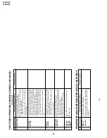
No.
Adjusment point
Conditions/Adjusting pr
ocedure
W
a
vef
orm or other
s
VIDEO AND
AUDIO
OUTPUT
CHECK
1.
Receiv
e the "P
AL Color Bar" signal (100%
White
Color Bar
, Sound 400 Hz 100% Mod C475)
2.
T
e
rm
inate the
Video output with a 75 ohm imped-
ance
. M
a
ke
sure the output is as specified (1.0
Vp-p
±
3 dB).
3.
T
e
rm
inate the A
udio output with a 10k ohm im-
pedance
. M
a
k
e
sure the O/P is as specified
(1.76 Vp-p
±
3 dB).
1
VIDEO AND
AUDIO INPUT
CHECK
1.
Using the
TV/A
V k
e
y on the remote controller
,
mak
e
sure that the modes change in order of
TV
,
A
V1, A
V2 &
TV again and the video & audio out-
put are according to the input terminal for each
mode.
2
A/V INPUT AND OUTPUT CHECKING
W
Y
Cy
G
M
g
R
B
(SAME LEVEL)
Summary of Contents for 14U10
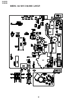
Page 22: ...14U10 15 14U20 25 22 MODEL 14U10 15 CHASSIS LAYOUT ...
Page 23: ...14U10 15 14U20 25 23 MODEL 14U20 25 CHASSIS LAYOUT ...
Page 24: ...14U10 15 14U20 25 14U10 15 14U20 25 24 25 BLOCK DIAGRAM 1 3 MODEL 14U10 15 MAIN BLOCK ...
Page 25: ...14U10 15 14U20 25 14U10 15 14U20 25 BLOCK DIAGRAM 2 3 MODEL 14U20 25 MAIN BLOCK 26 27 ...
Page 26: ...14U10 15 14U20 25 28 BLOCK DIAGRAM 3 3 MODEL 14U20 25 HEADPHONE BLOCK CRT BLOCK ...
Page 27: ...14U10 15 14U20 25 29 WAVEFORMS ...
Page 31: ...14U10 15 14U20 25 33 M E M O ...
Page 43: ...Ref No Part No Description Code Ref No Part No Description Code 49 14U10 15 14U20 25 ...


