


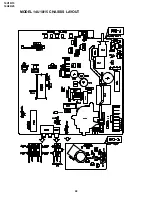


14U10/15
14U20/25
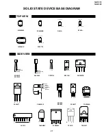
8
8-1
8-2
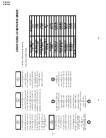
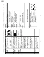
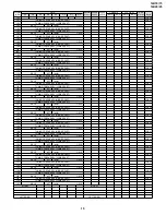
CUT
-OFF
, B
A
CKGR
OUND AND SUB-CONTRAST ADJUSTMENT
No.
Adjusment point
Conditions/Adjusting pr
ocedure
W
a
vef
orm or other
s
CR
T CUT
OFF
ADJUSTMENT
(I
2
C BUS
CONTROL)
1
.
Switch
TV to
VIDEO mode
, BLUE BA
CK OFF
, with
NO VIDEO signal.
2.
Press R/C to set Picture Normal condition.
3
.
Connect the oscilloscope to Red OUT from
IC801.(TP851)
Range
: 1 V/Div (DC)
Sweep
: 5 msec/Div
4
.
Adjust SCREEN
VR, so that the tip of signal reach
3.0 Vdc + 0.1 Vdc.
1
1 V
3.0Vdc
0
SUB-BRIGHT
-
NESS
ADJUSMENT
(I
2
C BUS
CONTROL)
1
.
Call " SUB-BRI" in service mode. (Receive Cross-
hatch pattern with 5 black level windows)
2.
Adjust the " SUB BRIGHT " bus data in order that
the line 1, 2 and 3 have the same darkness
whereas line 4 is slightly brighter than line 1, 2
and 3 and finally line 5 will be the brighter than
line 4.
2
1, 2, 3 are in same black level.
1 2 3 4 5
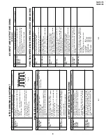
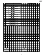
WHITE BAL-
ANCE SER
V
-
ICE MODE
ADJ. (I
2
C BUS
CONTROL)
1
.
Receive the "WHITE" pattern with BURST signal.
2.
Press R/C to set Picture NORMAL condition.
3.
Connect the DC miliammeter betw
een TP602
(-)
and TP603
(+).
4.
Check Beam current should be around 800
µ
A.
5.
Set it to ser
vice mode and adjust the " DRI-GS" &
"DRI-BS" data to ha
v
e
a colour temper
ature of
12,300
°
K ( white ). * Note .
6
.
Receiv
e "WHITE" patter
n, with B
URST signal, and
set Br
ightness
Y b
y
gener
ator
, to **10cd/m
2
Minolta CA-100) b
y reducing Luminate
Y signal.
7.
Adjust "CUT
-R" & "CUT
-G" to get 12,300
°
K .
Then
go back normal mode. (High Bright)** to check
colour temperature. If out of range, back to 1.
Note:
This adjustment must be done after
warming up the unit for 30 minutes or
longer with a beam current over 500
µ
A).
*
Adjust DRI-GC/GW
, DRI-BC/BW as f
ollo
wing
data, after finishing DRI-GS and DRI-BS:
DRI-
GC=DRI-GW="DRI-GS"-7:DRI-BW="DRI-BS"-
7:DRI-RC=25:DRI-BC=DRI-BS:DRI-R
W=32
**
Low=10cd/m
2
:High=200cd/m
2
3
*
12,300
°
K
X
: 0.272
Y
: 0.275
(MINOL
T
A
COLOUR ANAL
YZER
CA-100)
*Note:
Abo
v
e
Data can be UP/
DO
WN b
y
V
olume k
e
y.
Maximum
beam check
1.
Receive the "Monoscope Pattern" signal.
2.
Press R/C to set Picture NORMAL condition.
3.
Connect the DC miliammeter betw
een TP603
(+)
and TP602
(–
).
(Full Scale: 3 mA Range)
4.
Beam current must be within 800
±
100
µ
A.
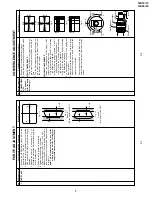
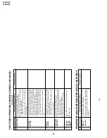
4
P
AL CHR
OMA ADJUSTMENT
No.
Adjusment point
Conditions/Adjusting pr
ocedure
W
a
vef
orm or other
s
SUB COLOUR
(I
2
C BUS
CONTROL)
1.
Receiv
e the "P
AL Colour Bar" signal.
2.
Press R/C to set Picture Normal condition.
3
.
Connect the oscilloscope to Red cathode(TP854).
»
Range
: 20
V/Div
. (A
C) (Using 10:1 probe)
»
Sw
eep time
:
10
µ
sec/Div
.
4
.
Using the R/C call "SUB COL" in SER
VICE mode
.
Adjust SUB COLOUR bus data, so that the 75%
White & Red por
tions of P
AL Colour Bar be at the
same le
v
el sho
wn as Fig.
1-1.
5.
Clear the SER
VICE mode
.
1
Cy
G
B
W
Y
100%W
75%
Mg
R
Fig. 1-1
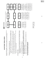
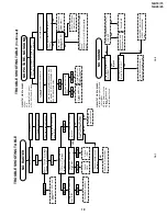
HORIZONT
AL AND
VER
TICAL DEFLECTION LOOP and Focus AD-
JUSTMENT
No.
Adjusment point
Conditions/Adjusting pr
ocedure
W
a
vef
orm or other
s
V
-SLOPE (I
2
C
BUS CON-
TROL)
V
-SHIFT
-50
(I
2
C B
U
S
CONTR
OL)
V - AMP 50 (I
2
C
BUS CON-
TROL)
S-CORREC-
TION
(I
2
C BUS
CONTROL)
H - SHIFT (50)
(H-CENTER)
(I
2
C BUS
CONTROL)
1.
Receive Monoscope Pattern Signal.
2.
Call the "V
-LIN" mode
.
3.
Increase or decrease "V
-LIN" b
y
V
olume k
e
y till
the horizontal line in the center of monoscope is
just at the position where the blanking starts.
1.
Call the "V
-CENT" mode
.
2.
Increase or decrease "V
-CENT" b
y
V
olume k
e
y
till the picture is centered.
1.
Call the "V
-AMP" mode
.
2.
Increase or decrease "V - AMP" b
y V
olume
k
e
y
to set overscan of 9.5% typical.
Adjustment Spec 9.5% range +1% -0%.
FIXED D
A
T
A
, NO NEED
T
O
ADJUST
.
1.
Call the "H-CENT" mode.
2.
Increase or decrease "H-CENT" b
y V
olume
k
e
y
to center the picture horizontal.
1
2
3
4
5
FOCUS
1.
Receive the "Monoscope Pattern" signal.
2.
Press R/C to set Picture NORMAL condition.
3.
Adjust the f
ocus control to get the best f
ocusing.
6
Summary of Contents for 14U10
Page 22: ...14U10 15 14U20 25 22 MODEL 14U10 15 CHASSIS LAYOUT ...
Page 23: ...14U10 15 14U20 25 23 MODEL 14U20 25 CHASSIS LAYOUT ...
Page 24: ...14U10 15 14U20 25 14U10 15 14U20 25 24 25 BLOCK DIAGRAM 1 3 MODEL 14U10 15 MAIN BLOCK ...
Page 25: ...14U10 15 14U20 25 14U10 15 14U20 25 BLOCK DIAGRAM 2 3 MODEL 14U20 25 MAIN BLOCK 26 27 ...
Page 26: ...14U10 15 14U20 25 28 BLOCK DIAGRAM 3 3 MODEL 14U20 25 HEADPHONE BLOCK CRT BLOCK ...
Page 27: ...14U10 15 14U20 25 29 WAVEFORMS ...
Page 31: ...14U10 15 14U20 25 33 M E M O ...
Page 43: ...Ref No Part No Description Code Ref No Part No Description Code 49 14U10 15 14U20 25 ...


