14U10/15
14U20/25
10
10-1
10-2
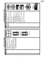
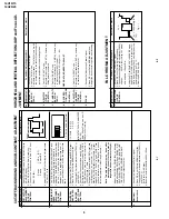
No.
Adjusment point
Conditions/Adjusting pr
ocedure
W
a
vef
orm or other
s
8
WHITE TEMP
1.
Receiv
e "Monoscope P
atter
n" signal.
2.
Set FUNCTION to select
WHITE TEMP
.
3
.
Press
V
olume Up/Do
wn k
e
y to chec
k
WHITE
TEMP Option, ST
AND
ARD:
NORMAL SETTING,
W
ARM f
or more REDDISH
direction changing, COOL for more BLUISH di-
rection changing.
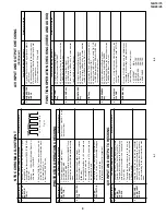
FUNCTION OPERA
TION CHECKING (VIDEO AND A
UDIO)
(Contin
ued)
1.
Receiv
e the "P
AL COLOUR BAR" signal, press
the COLOUR SYSTEM key to select modes ex-
cept P
AL, chec
k the COLOUR is not w
or
king prop-
er
ly
.
Then, select the "P
AL" mode
. Chec
k
again
its colour so that it is w
or
king properly
.
2
.
Receiv
e "NTSC 4.43/3.58" signal, press COLOUR
SYSTEM k
e
y to select modes e
xcept NTSC4.43/
3.58, chec
k the COLOUR is not w
or
king prop-
er
ly
.
Then, select the "NTSC 4.43/3.58" mode
.
Chec
k again its colour so that it is w
or
king prop-
er
ly
.
1
.
Receiv
e "P
AL-B/G" signal, press the "SOUND
SYSTEM" to select D/K, I.
Chec
k the sound out-
put is not wor
king proper
ly
.
Select B/G and chec
k the sound output to mak
e
sure it is w
o
rking propely
.
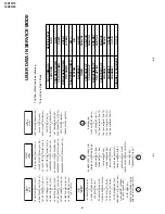
COLOUR
SYSTEM
9
SOUND
SYSTEM
10
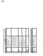
HEADPHONE J
A
CK CHECKING (FOR 14U20 & 14U25 ONL
Y)
No.
Adjusment point
Conditions/Adjusting pr
ocedure
W
a
vef
orm or other
s
HEADPHONE
OUTPUT
CHECKING
1.
Receiv
e P
AL COLOUR P
AR with SOUND 400Hz,
100% MODULA
TION (
±
50kHz De
v).
2
.
Maximum volume, and check the headphone
output with 400Hz sound and no sound out from
speak
er
.
1
Chec
k OSD LANGU
A
GE quantity and type as be-
low:
ENGLISH, only
.
1.
Receiv
e "P
AL COLOUR BAR" signal.
2.
T
u
rn
up the v
o
lume control to maxim
um, mak
e
sure the sound is heard from the speak
ers
.
Then
put the unit in no signal state.
3.
Chec
k the sound mute is eff
ectiv
e
.
4.
Finally turn sound level of CTV to minimum.
NOISE MUTE
CHECKING
11
OSD LAN-
GUAGE
QUANTITY
CHECK
12
Summary of Contents for 14U10
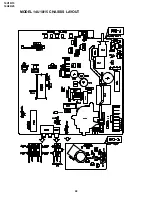
Page 22: ...14U10 15 14U20 25 22 MODEL 14U10 15 CHASSIS LAYOUT ...
Page 23: ...14U10 15 14U20 25 23 MODEL 14U20 25 CHASSIS LAYOUT ...
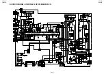
Page 24: ...14U10 15 14U20 25 14U10 15 14U20 25 24 25 BLOCK DIAGRAM 1 3 MODEL 14U10 15 MAIN BLOCK ...
Page 25: ...14U10 15 14U20 25 14U10 15 14U20 25 BLOCK DIAGRAM 2 3 MODEL 14U20 25 MAIN BLOCK 26 27 ...
Page 26: ...14U10 15 14U20 25 28 BLOCK DIAGRAM 3 3 MODEL 14U20 25 HEADPHONE BLOCK CRT BLOCK ...
Page 27: ...14U10 15 14U20 25 29 WAVEFORMS ...
Page 31: ...14U10 15 14U20 25 33 M E M O ...
Page 43: ...Ref No Part No Description Code Ref No Part No Description Code 49 14U10 15 14U20 25 ...


