


14U10/15
14U20/25
2
2-1
2-2
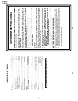
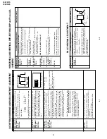
IMPOR
T
ANT SER
VICE NO
TES
Maintenance and repair of this receiver should be done by qualified
ser
vice per
sonnel onl
y.
SER
VICE OF HIGH
V
O
L
T
A
GE SYSTEM AND PIC-
TURE TUBE
When servicing the high voltage system, remove static charge from it by
Connecting a 10K ohm Resistor in series with an insulated wire(such as a
test pr
obe) between picture tube da
g and 2nd anode lead.
(A
C line cor
d
should be disconnected fr
om A
C
outlet.)
1.
Picture tube in this receiver emplo
ys integral implosion pr
otection.
2.
Replace with tube of the same type n
umber f
or contin
ued saf
ety
.
3.
Do not lift picture tube by the neck.
4.
Handle the picture tube only when wearing shatterproof goggles and after discharging
the high v
olta
g
e
completel
y
.
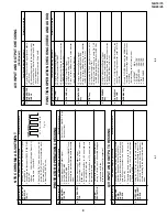
X-RA
Y
This receiver is designed so that any X-Ray radiation is kept to an absolute
Minimum. Since certain malfunctions or servicing may produce potentially
hazardous radiation with prolonged exposure at close range, the followin
precautions should be observed:
1.
When repairing the circuit, be sure not to increase the high voltage to more than 25.8kV
(at beam 0
µ
A) for the set.
2.
T
o
keep the set in a normal opear
tion,
be sure to make it function on 22.8kV
±
1.5kV (at
beam 800
µ
A) in the case of the set.
The set has been factor
y - Adjusted to the abo
ve-
mentioned high voltage.
∴
If there is a possibility that the high voltage fluctuates as a result of the repairs,
never forget to check for such high voltage after the work.
3.
Do not substitute a picture tube with unauthorizerd types and/or brands which may
cause excess X-ray radiation.
BEFORE RETURNING THE RECEIVER
Bef
ore returning the receiver to the user
, perf
orm the f
ollo
wing saf
ety Chec
ks.
1.
Inspect all lead dress to make cer
tain that leads are not pinc
hed or that har
d
ware is not
lodged between the c
hassis and other metal par
ts in the receiver
.
2.
Inspect all protective devices such as non-metallic control knobs, insulating fishpapers,
cabinet backs, adjustment and compartment covers or shields, isolation resistor- ca-
pacity networks, mechanical insulators etc.
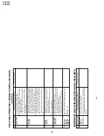
SPECIFICA
TIONS
Con
v
ergence
.................................................................
Self Con
v
e
rgence System
F
ocus
............................................................
Electrostatic F
ocus High Bi-P
otential
Sw
eep Deflection
.....................................................................................
Magnetic
Intermediate Frequencies
Picture IF Carrier
..................................................................................
38.9MHz
Sound IF Carrier Frequency
5.5MHz
...............................................................................................
33.4MHz
Colour Sub-Carrier Frequency
...........................................................
34.47MHz
Power Input
.....................................................................
100 ~ 240V A
C
50/60 Hz
P
o
w
e
r Consumption
........................................................................................
70W
A
udio P
o
w
e
r Output Rating
..............................................................
5.0W(at Max.)
Speaker
Size
....................................................................................
10 cm Round (2pcs
.)
V
o
ice Coil Impedance
............................................................
16 ohms at 400 Hz
Aerial Input Impedance
VHF/UHF
...........................................................................
75 ohms Unbalanced
T
uner Ranges
VHF-Channels
...............................................
1(44.25MHz) thr
u 11(224.25MHz)
UHF-Channels
..........................................
21(471.25MHz) thr
u 69(855.25MHz)
Dimensions
...................................................................................
Width: 509.0mm
Height: 335.0mm
Depth: 369.0mm
W
e
ight(appro
x
):
12.9 kg
Cabinet mater
ial
....................................................................................
All Plastics
Specifications are subject to change without prior notice.
Summary of Contents for 14U10
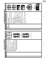
Page 22: ...14U10 15 14U20 25 22 MODEL 14U10 15 CHASSIS LAYOUT ...
Page 23: ...14U10 15 14U20 25 23 MODEL 14U20 25 CHASSIS LAYOUT ...
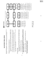
Page 24: ...14U10 15 14U20 25 14U10 15 14U20 25 24 25 BLOCK DIAGRAM 1 3 MODEL 14U10 15 MAIN BLOCK ...
Page 25: ...14U10 15 14U20 25 14U10 15 14U20 25 BLOCK DIAGRAM 2 3 MODEL 14U20 25 MAIN BLOCK 26 27 ...
Page 26: ...14U10 15 14U20 25 28 BLOCK DIAGRAM 3 3 MODEL 14U20 25 HEADPHONE BLOCK CRT BLOCK ...
Page 27: ...14U10 15 14U20 25 29 WAVEFORMS ...
Page 31: ...14U10 15 14U20 25 33 M E M O ...
Page 43: ...Ref No Part No Description Code Ref No Part No Description Code 49 14U10 15 14U20 25 ...


