


8
13VT-R100/R150
13VT-CR10
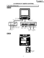
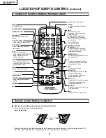
LOCATION OF USER'S CONTROL
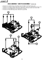
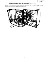
(Continued)
Location Of Control’s Buttons (Remote Control)
Remote Control Battery Installation
INPUT
TV/VIDEO Select
POWER ON/OFF
CHANNEL SELECT
FLASHBACK
Returns to previously viewed
channel.
COUNTER RESET
• Used to reset the tape counter.
TAPE SPEED
• Used to select the recording
tape speed.
PLAY
• Used for tape playback.
• Used to cancel the PAUSE/STILL
mode and return to normal
playback operation.
REW
• Used to rewind the tape or to
conduct Reverse Video Search
during playback mode.
REC
• Used to record a program.
–, +
TIMER ON/OFF
CONFIRM
• Used to confirm the program
setting.
RETURN
SET
1
2
3
4
5
6
7
8
9
0
100
POWER
INPUT
DISPLAY
MUTE
VOL
TAPE
SPEED
REC
REW
FF
PLAY
STOP
PAUSE/STILL
COUNTER
RESET
DPSS
FLASHBACK
TAMPER
PROOF
TV • VCR COMBINATION
+
SET
PROG
MENU
TIMER
ON/OFF
CONFIRM
–
±
—
±
TR
•
•
•
•
—
RETURN
CH
•
Infrared Transmitter Window
DISPLAY
• Used to change the On Screen
Display.
MUTE
Press
→
Mutes sound.
Press again
→
Restores sound
to previous level.
Press the MUTE button to enter
the CLOSED CAPTION mode
automatically if the signal contains
CC information.
VOLUME UP/DOWN
CHANNEL UP/DOWN
(TRACKING
±
/
—
)
• Used to select the CHANNEL.
• Used to adjust the TRACKING
while playing the tape.
TAMPER PROOF
• Used to block changes to current
operating mode.
FF
• Used to fast forward the tape or
to conduct Forward Video Search
during playback mode.
STOP
• Used to stop the tape.
PAUSE/STILL
• Used to temporarily stop the tape
during recording mode.
• Used to display a still picture
during playback mode.
DPSS (
±
/
—
)
• Press the (
±
/
—
) button to search
for the index signal and begin
playback automatically.
PROGRAM
• Press the button to enter the Timer
Recording mode.
MENU
• Used to select the menu screen.
Ë
Before using the television, prepare the Remote Control
To use the remote control, insert batteries first.
Insert the batteries
• With your thumb nail, pull up the slit as indicated by the arrow to remove the back cover. Insert two batteries (size “AA”).
Be sure to match the battery
±
/
—
terminals with the
±
/
—
marks inside the compartment.
Battery
Cover
Pull up
Summary of Contents for 13VT-CR10
Page 64: ...71 13VT R100 R150 13VT CR10 6 5 4 3 2 1 A B C D E F G H SCHEMATIC DIAGRAM CRT Unit ...
Page 72: ...85 13VT R100 R150 13VT CR10 6 5 4 3 2 1 A B C D E F G H PWB C POWER Unit Component Side ...
Page 73: ...86 13VT R100 R150 13VT CR10 6 5 4 3 2 1 A B C D E F G H PWB A MAIN Unit Component Side ...
Page 74: ...87 13VT R100 R150 13VT CR10 6 5 4 3 2 1 A B C D E F G H PWB A MAIN Unit Chip Parts Side ...