


38
13VT-R100/R150
13VT-CR10
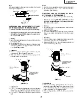
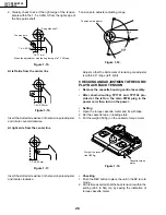
INSTALLING THE MASTER CAM (AT REAR
SIDE OF MECHANISM CHASSIS)
1. Make sure beforehand that the shifter is at the point as
shown below.
2. Place the master cam in the position as shown below.
Note:
See the figure below for the phase matching between the
master cam and the casecon drive gear.
3. Finally fix with the E-ring.
Figure 1-44-2.
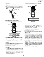
When installing the master cam,
align the casecon drive gear
round mark with the half-round
notch of master cam.
E-ring
(XRESJ30-06000)
Master cam
Fully turn
clockwise
Fully turn counterclockwise
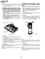
Figure 1-44-1.
Face the wide tooth side ward
Master cam
Casecon drive gear
10.2 mm
Round mark
Half-round notch
+0
.2
–0.2
Apply grease
No grease
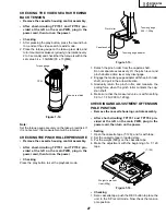
REPLACEMENT OF LOADING MOTOR
• Removal
• Replacement
1. Remove the loading motor, and install the replace-
ment loading motor as shown below.
Figure 1-46.
The loading motor pressing-in must be less than
14.7 N (15 gf).
Adjust the distance between motor and pulley to
10.2 mm).
Figure 1-45.
Apply grease
+0
.2
–0.2
Summary of Contents for 13VT-CR10
Page 64: ...71 13VT R100 R150 13VT CR10 6 5 4 3 2 1 A B C D E F G H SCHEMATIC DIAGRAM CRT Unit ...
Page 72: ...85 13VT R100 R150 13VT CR10 6 5 4 3 2 1 A B C D E F G H PWB C POWER Unit Component Side ...
Page 73: ...86 13VT R100 R150 13VT CR10 6 5 4 3 2 1 A B C D E F G H PWB A MAIN Unit Component Side ...
Page 74: ...87 13VT R100 R150 13VT CR10 6 5 4 3 2 1 A B C D E F G H PWB A MAIN Unit Chip Parts Side ...