


16
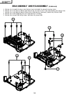
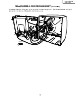
13VT-R100/R150
13VT-CR10
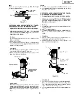
Vertical-Size Adjustment
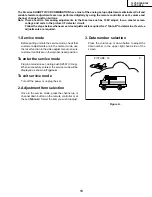
1. Select a good local channel.
2. Enter the service mode and select the service
adjustment item "V-AMP".
3. While observing the top and bottom of the screen,
adjust "V-AMP" data value to proper vertical size and
linearity.
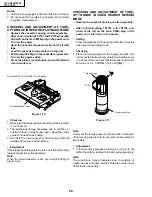
Horizontal Position Adjustment
1. Select a good local channel.
2. Enter the service mode and select the service
adjustment item "H-PHASE".
3. Adjust "H-PHASE" data value so that picture is
centered.
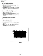
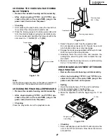
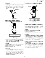
Caption Position Adjustment
(Horizontal)
1. Select a good local channel.
2. Enter the service mode and select the service
adjustment item "TEXT BOX".
3. A black text box appears on the screen. (See Figure
B. below.)
4. Adjust "TEXT BOX" data value so that text box is
positioned in the center of the screen.
Figure B.
Summary of Contents for 13VT-CR10
Page 64: ...71 13VT R100 R150 13VT CR10 6 5 4 3 2 1 A B C D E F G H SCHEMATIC DIAGRAM CRT Unit ...
Page 72: ...85 13VT R100 R150 13VT CR10 6 5 4 3 2 1 A B C D E F G H PWB C POWER Unit Component Side ...
Page 73: ...86 13VT R100 R150 13VT CR10 6 5 4 3 2 1 A B C D E F G H PWB A MAIN Unit Component Side ...
Page 74: ...87 13VT R100 R150 13VT CR10 6 5 4 3 2 1 A B C D E F G H PWB A MAIN Unit Chip Parts Side ...


