


45
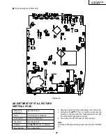
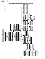
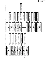
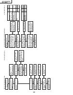
13VT-R100/R150
13VT-CR10
NO
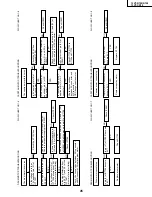
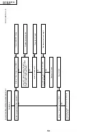
DRUM MOTOR TROUBLESHOOTING
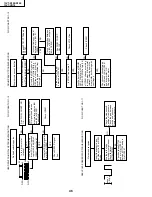
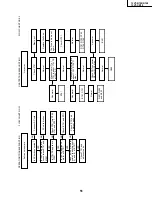
DRUM MOTOR TROUBLESHOOTING
FLOW CHART NO.1-6
FLOW CHART NO.1-7
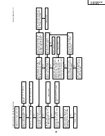
CAPSTAN MOTOR TROUBLESHOOTING
FLOW CHART NO.1-8
The drum motor fails to run.
The capstan motor fails to run.
Drum motor cannot stop.
YES
YES
YES
YES
YES
YES
YES
YES
YES
YES
YES
YES
Is 2.5V applied at pin (69) of
IC2201?
Is 5V applied at pin (8) of
AC connector?
Is the voltage about 2.6V
applied at pin (4) of AC
connector?
Is the voltage about 3.5V
applied at pin (3) of AC
connector?
Check the connection
between AC connector and
MC connector.
OR Change capstan motor.
Check the AT 5V line
(around IC756).
Is the PWM signal detected
at pin (31) and (33) of
IC2001?
Check the connection between AD connector
and ME connector. Or replace drum motor.
Check the AT 12V line.
Check IC2201.
Check IC2001.
Check IC7706.
Is the voltage more than
12V applied at pin (21) of
IC7706?
Is the voltage at pin (2) of
IC7706 become about 2.6V?
(drum motor rotator timing)
Is pin (2) of IC7706 become
0.6V?
Replace drum motor.
Check R7759.
Is pin (47) of IC2001 become
0 V?
Is the signal detected from
pin (16),(17) and (18) of the
IC7706?
(drum motor rotator timing)
NO
Check whether pin (70) of IC2201 is 2.5V.
Check input power supply pin of IC2201.
Check the connection between pin (32) and pin (34)
of IC2001 and all the way up to pin(2) of IC7706
Check the connection between pin (31) and (33) of
IC2001 and pin (4) of AC connector.
NO
Is there PWM signal at pin
(32) and (34) of IC2201?
NO
NO
NO
NO
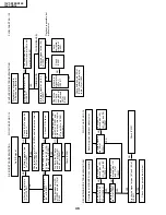
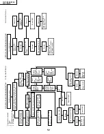
CAPSTAN MOTOR TROUBLESHOOTING
FLOW CHART NO.1-9
Capstan motor cannot stop.
YES
YES
Is pin (4) of AC connector
become 0 V?
Is pin (29) of IC2001
become 0 V?
Replace R7754.
NO
NO
Is 5V detected at pin (92) of
IC2001?
Check R7732, R7734 to
R7736 and C7730.
Check IC2001.
NO
Check IC2001.
NO
NO
NO
Check IC2001.
NO
Replace capstan motor.
Summary of Contents for 13VT-CR10
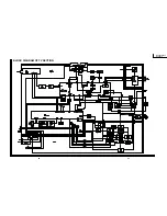
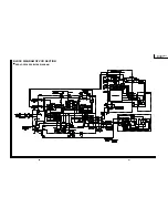
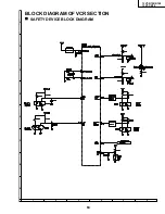
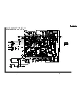
Page 64: ...71 13VT R100 R150 13VT CR10 6 5 4 3 2 1 A B C D E F G H SCHEMATIC DIAGRAM CRT Unit ...
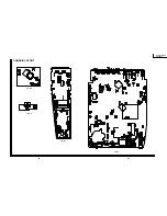
Page 72: ...85 13VT R100 R150 13VT CR10 6 5 4 3 2 1 A B C D E F G H PWB C POWER Unit Component Side ...
Page 73: ...86 13VT R100 R150 13VT CR10 6 5 4 3 2 1 A B C D E F G H PWB A MAIN Unit Component Side ...
Page 74: ...87 13VT R100 R150 13VT CR10 6 5 4 3 2 1 A B C D E F G H PWB A MAIN Unit Chip Parts Side ...


