


37
13VT-R100/R150
13VT-CR10
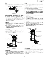
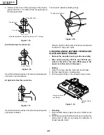
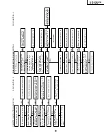
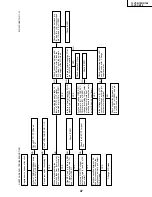
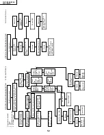
INSTALLING THE SHIFTER
Figure 1-42.
Capstan
D.D. motor
Drum
Reel pulley
(Bottom side of mechanism chassis)
Sifter
Phase-Matching
point
2
Insert
point
1
Half round notch
Shaft
1
Round mark
Loading gear (T)
Insert
point
3
Insert
point
2
Insert
point
4
Insert
point
6
Release
point
3
Shaft
1
Shaft
1
Shaft
2
1. Make sure that the loading gear is at the point
1
as
shown below.
2. Install, paying attention to
6
insertion points and
3
release points.
3. For the phase matching at the insertion point
1
, see
the point
2
as shown below.
4. Finally fix the inserts
1
and
4
.
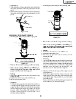
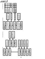
Figure 1-43.
Rotation
point
2
Phase-matching
point
1
Summary of Contents for 13VT-CR10
Page 64: ...71 13VT R100 R150 13VT CR10 6 5 4 3 2 1 A B C D E F G H SCHEMATIC DIAGRAM CRT Unit ...
Page 72: ...85 13VT R100 R150 13VT CR10 6 5 4 3 2 1 A B C D E F G H PWB C POWER Unit Component Side ...
Page 73: ...86 13VT R100 R150 13VT CR10 6 5 4 3 2 1 A B C D E F G H PWB A MAIN Unit Component Side ...
Page 74: ...87 13VT R100 R150 13VT CR10 6 5 4 3 2 1 A B C D E F G H PWB A MAIN Unit Chip Parts Side ...