


5
Electrical installation
Installation instructions (all versions)
Operating Instructions – MOVIFIT
®
MC
43
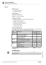
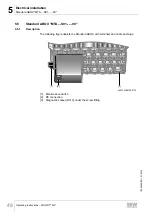
Example 1
MOVIFIT
®
MC with:
• "Classic" function level
• PROFINET IO interface
• S12A safety option
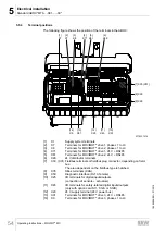
Type designation
EBOX: MTM11A000-E20A-00\S12A
ABOX: MTA11A-503-S613-M01-00
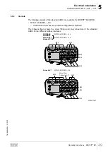
Connected components
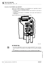
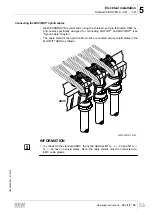
The following components are connected to the MOVIFIT
®
unit:
• 3 MOVIMOT
®
MM..D inverters
• 0 sensors
• 0 actuators
• 4 sensors (safety related) each with 50 mA (1.2 W)
• 1 actuator (safety related) with 200 mA (4.8 W)
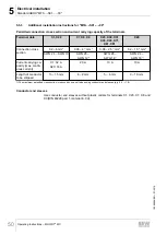
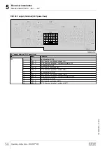
Current and power demand
The following table shows the current and power demands of the components that
must be taken into account when dimensioning the 24 V supply:
24 V
voltage lev-
el
Component
Current
demand
Power
at
V
IN
= 24 V
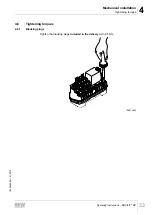
24V_C
MOVIFIT
®
control electronics
"Classic" PROFINET IO
250 mA
6.0 W
0 sensors at DI00 to DI11
(VO24_I to VO24_III)
–
–
24V_S
0 sensors at DI12 to DI15.. (VO24_IV)
–
–
0 actuators at DO00, DO03 (VO24_IV)
–
–
24V_P
3 x MOVIMOT
®
MM..D
3 x 120 mA
3 x 2.9 W
24V_O
S12A safety option
100 mA
2.4 W
4 sensors at F-DI.. (F-SS0, F-SS1)
200 mA
4.8 W
1 actuator at F-DO..
200 mA
4.8 W
Total consumption
of the MOVIFIT
®
unit (incl.
MOVIMOT
®
):
1110 mA
26.7 W
INFORMATION
The current and power demands (400 V) of the connected MOVIMOT
®
drives are not
taken into account.
19484828/EN – 01/2015


