


5
Electrical installation
Installation instructions (all versions)
Operating Instructions – MOVIFIT
®
MC
41
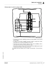
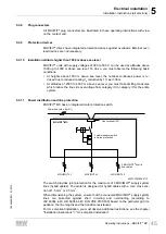
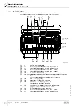
24V_O = Option supply
The 24V_O voltage level supplies:
• the integrated option card S11, S12A or S12B
• and the sensor/actuator interfaces on the S11 option card.
With PROFIsafe option S11 and safety option S12, the complete safety electronics
and the safe inputs/outputs are supplied from 24V_O.
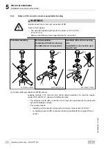
WARNING
Danger with applications with safe disconnection due to incorrect safe disconnec-
tion.
Severe or fatal injuries.
• If you use MOVIFIT
®
with the PROFIsafe option S11, observe the permissible
wiring diagrams as well as the safety conditions specified in the "MOVIFIT
®
MC /
FC – Functional Safety" manual.
• If you use MOVIFIT
®
with the safety option S12, observe the permissible wiring
diagrams as well as the safety conditions specified in the "MOVIFIT
®
MC / FC –
Functional Safety with Safety Option S12" manual.
Depending on the application, the 24V_O voltage level is supplied by:
• The 24V_C voltage level
• The 24V_S voltage level (via jumpers at terminal X29)
• An external source
Note that the entire S11/S12 option card with the connected sensors and actuators is
no longer supplied when the voltage level is disconnected. This causes an error mes-
sage.
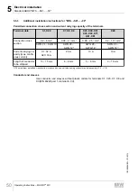
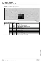
Connection of voltages
Connect the 24V_C and 24V_S voltage levels to terminal X20 with a large cable cross
section. Loop the 24V_C and 24V_S voltage levels through to the next MOVIFIT
®
unit
as "24 V power bus" with a large cable cross section.
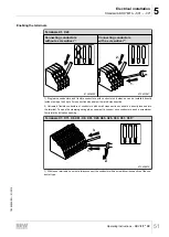
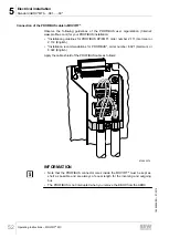
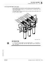
Connect the 24V_P and 24V_O voltage levels to terminal X29.
INFORMATION
• For connection examples, refer to chapter "Power bus connection exam-
→
• For the permitted connection cross sections, refer to chapter "Standard ABOX.." >
Additional installation instructions" > "Permitted connection cross section".
19484828/EN – 01/2015


