SEW-Eurodrive R17 DRS71S4 Assembly And Operating Instructions Manual Download Page 49

48

Assembly and Operating Instructions – Gear Units R..7, F..7, K..7, K..9, S..7, SPIROPLAN® W

4

Shaft-mounted gear units with TorqLOC

®

Mechanical Installation

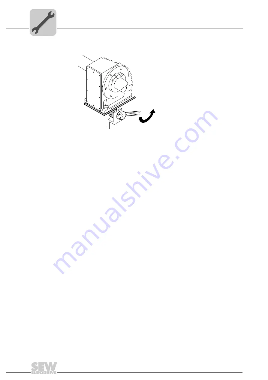
18.Securely tighten the torque arm; observe chapter "Torque arm for shaft-mounted

gear units" (page 29).

5129142283

Artisan Technology Group - Quality Instrumentation ... Guaranteed | (888) 88-SOURCE | www.artisantg.com

Summary of Contents for R17 DRS71S4

Page 1: ...nderutilized and idle equipment along with credit for buybacks and trade ins Custom engineering so your equipment works exactly as you specify Critical and expedited services Leasing Rentals Demos In...

Page 2: ...ion System Integration Services Assembly and Operating Instructions Gear Units R 7 F 7 K 7 K 9 S 7 SPIROPLAN W Edition 10 2013 20200544 EN Artisan Technology Group Quality Instrumentation Guaranteed 8...

Page 3: ...SEW EURODRIVE Driving the world Artisan Technology Group Quality Instrumentation Guaranteed 888 88 SOURCE www artisantg com...

Page 4: ...f helical bevel gear units K 9 12 3 4 Basic structure of helical bevel gear units K 37 K 187 13 3 5 Basic structure of helical worm gear units 14 3 6 Basic structure of SPIROPLAN gear units W 10 W 30...

Page 5: ...AD input shaft assembly 88 6 6 Inspection maintenance for the gear unit 89 7 Mounting Positions 104 7 1 Designation of the mounting positions 104 7 2 Churning losses 105 7 3 Mounting position MX 105...

Page 6: ...operty and other notes 1 2 2 Design of the section related safety notes Section related safety notes do not apply to a specific action but to several actions per taining to one subject The symbols use...

Page 7: ...y with the information contained in this documentation to ensure safe operation and to achieve the specified product characteristics and performance fea tures SEW EURODRIVE assumes no liability for in...

Page 8: ...provides additional information WARNING Danger of fatal injury or risk of injury during the operation of motors or gearmotors caused by live bare in the event of open connectors terminal boxes and mov...

Page 9: ...must only be carried out by persons who are trained appropriately All qualified personnel must wear appropriate protective clothing 2 4 Designated use The gear unit series R 7 F 7 K 7 K 9 S 7 SPIROPLA...

Page 10: ...al measures before startup 2 7 Setup Observe the notes in the Mechanical Installation section 2 8 Startup operation Check the oil level before startup as described in chapter Inspection Maintenance pa...

Page 11: ...g bearing bearing Retaining ring Spacer tube 19 20 22 24 25 30 31 32 34 37 39 41 Key Breather valve Gear unit housing Eyebolt Rolling bearing Rolling bearing Key Spacer tube Rolling bearing Rolling be...

Page 12: ...ng bearing Key Spacer tube Rolling bearing Retaining ring Retaining ring Rolling bearing Key Rolling bearing Screw plug Shield ring Retaining ring 91 92 93 94 100 101 102 131 160 161 165 181 183 Retai...

Page 13: ...using stage 1 Gasket Stud Tapered roller bearing Key Gasket Tapered roller bearing Supporting ring only K 29 Screw plug Screw plug Thread reduction 80 88 89 106 115 141 150 159 163 167 183 518 519 Key...

Page 14: ...ring Rolling bearing Key Rolling bearing Screw plug Shield ring Shield ring Retaining ring Closing cap Inspection cover Hex head screw 102 113 114 116 119 131 132 133 135 161 506 507 508 521 521 Gask...

Page 15: ...39 43 59 61 Breather valve Gear unit housing Rolling bearing Rolling bearing Rolling bearing Retaining ring Key Screw plug Retaining ring 88 89 100 101 102 131 137 506 507 Retaining ring Closing cap...

Page 16: ...19 22 25 65 66 68 71 72 Key Gear unit housing Rolling bearing Oil seal Rolling bearing bearing Retaining ring Supporting ring Retaining ring 88 89 100 101 102 143 250 251 Retaining ring Closing cap In...

Page 17: ...g Key 22 25 26 30 31 32 33 36 37 44 Gear unit housing Deep groove ball bearing Housing stage 1 Deep groove ball bearing Key Spacer tube Retaining ring Hex head screw Deep groove ball bearing O ring 59...

Page 18: ...aximum permitted output speed Mamax Nm Maximum permitted output torque Memax Nm Maximum permitted input torque i Gear unit ratio IM Mounting position 76646 Bruchsal na Mamax Nm Memax Nm IM i kg M1A 70...

Page 19: ...and output elements Lubricant e g NOCO Fluid Bolt locking compound for input shaft assembly with centering shoulder e g Loctite 243 Standard parts are not included in the delivery 4 1 1 Installation...

Page 20: ...ing to the technical documentation nameplate and lubricant table in section Lubricants No harmful oils acids gases vapors radiation etc in the vicinity For special designs The drive is designed in acc...

Page 21: ...57B are mounted both via the torque arm and via the foot plate Risk of injuries and damage to property Especially with the KA 9B T variant it is not permitted to use the foot plates and the torque arm...

Page 22: ...on of the breather valve accordingly in the event of a change of mounting position Observe chapter Lubricant fill quan tities and chapter Mounting Positions Consult the SEW customer service if you int...

Page 23: ...tening torques Bolt nut Tightening torque screw nut Strength class 8 8 Nm M6 11 M8 25 M10 48 M12 86 M16 210 M20 410 M24 710 M30 1450 M36 2500 M42 4600 M48 6950 M56 11100 Flange Gear unit Bolt nut Tigh...

Page 24: ...cting the cus tomer flange To improve the friction contact between flange and mounting surface SEW EURODRIVE recommends anaerobic gaskets or an anaerobic glue Screw Gear unit type R R F RX F FH B FA B...

Page 25: ...Flange mm Screw RF R F RM FF FAF FHF KF KAF KHF KVF SF SAF SHF WF WAF 80 M6 10 110 M8 20 120 M6 07 17 27 19 37 10 20 30 37 140 M8 07 17 27 37 47 160 M8 07 17 27 37 47 27 37 19 29 37 37 47 30 37 47 200...

Page 26: ...M1 M3 M5 and M6 SPIROPLAN W 10 W 20 W 30 gear units SPIROPLAN W 37 W 47 gear units in mounting positions M1 M2 M3 M5 and M6 K 19 K 29 gear units in mounting positions M1 M2 M3 M5 and M6 SEW EURODRIVE...

Page 27: ...activated If the breather valve has not been acti vated you must remove the transportation protection device from the breather valve be fore starting up the gear unit 1 Breather valve with transporta...

Page 28: ...ips after painting INFORMATION Mounting is easier if you first apply lubricant to the output element or heat it up briefly to 80 100 C NOTICE Bearing hosing or shaft may be damaged due to improper ass...

Page 29: ...urer s specifica tions when mounting couplings a Maximum and minimum clearance b Axial offset c Angular offset 211364235 1 Hub A Unfavorable B Correct A B 1 1 INFORMATION Mounting is easier if you fir...

Page 30: ...ached according to the table NOTICE Improper mounting may result in damage to the gear unit Possible damage to property Do not place torque arms under strain when mounting Use screws of quality 8 8 to...

Page 31: ...he toque arm for helical bevel gear units Apply bearings to both sides of the bushing 1 Mount connection side B so that it mirrors A 7717631499 Gear unit Screws Tightening torque K 19 T 4 x M8 22 8 8...

Page 32: ...OPLAN W gear units Apply bearings to both sides of the bushing 1 211491723 Gear unit Screws Tightening torque S 37 T 4 x M6 16 8 8 11 Nm S 47 T 4 x M8 20 8 8 25 Nm S 57 T 6 x M8 20 8 8 25 Nm S 67 T 4...

Page 33: ...three mounting types 2A Standard scope of delivery 2B Installation removal kit for customer shaft with contact shoulder 2C Installation removal kit for customer shaft without contact shoulder 2A Insta...

Page 34: ...t shoulder 2C Installation with SEW EURODRIVE installation and removal kit page 37 Customer shaft without contact shoulder 211520523 1 Retaining screw 2 Lock washer 3 Washer 4 Retaining ring 5 Custome...

Page 35: ...hten the retaining screw to the appropriate torque see table 211524875 Screw Tightening torque Nm M5 5 M6 8 M10 12 20 M16 40 M20 80 M24 200 INFORMATION To avoid contact corrosion we recommend that the...

Page 36: ...W EURODRIVE Observe section Installation notes page 32 2B or 2C 1 Loosen the retaining screw 1 2 Remove parts 2 to 4 and if fitted the spacer tube 5 3 Insert the forcing disc 8 and the fixed nut 7 fro...

Page 37: ...llow shaft Mechanical Installation 5 Screw the retaining screw 1 back in Now you can force the gear unit off the shaft by tightening the screw 211529227 1 Retaining screw 4 Retaining ring 6 Customer s...

Page 38: ...47 WA 47 KA 29 25 M10 5 10 20 7 5 28 24 7 35 643 684 6 FA 37 KA 37 SA 47 SA 57 WA 47 KA 29 30 M10 5 10 25 7 5 33 29 7 35 643 685 4 FA 47 KA 47 SA 57 35 M12 5 12 29 9 5 38 34 7 45 643 686 2 FA 57 KA 5...

Page 39: ...You must always check whether this design can compensate the axial loads In particular applications e g mounting mixer shafts a different design may have to be used to secure the shaft axially In thes...

Page 40: ...y a few turns do not unscrew them completely 2 Carefully degrease the hollow shaft hole and the input shaft using a commercially available solvent NOTICE Tightening the screws without installed shaft...

Page 41: ...to the input shaft in the area of the bushing It is essential to make sure that the clamping area of the shrink disk is free from grease Never apply NOCO fluid directly to the bushing This is because...

Page 42: ...out shaft shoulder Install the shrink disk with a 1 to 2 mm distance from the gear unit housing Tighten the locking screws by working round with the torque wrench several times from one screw to the n...

Page 43: ...and the end of the shaft beforehand 4 Remove the shrink disk from the hub 4 7 3 Cleaning and lubrication There is no need to dismantle removed shrink disks before re installing them Clean and lubrica...

Page 44: ...customer shaft and the inside of the hollow shaft Ensure that all traces of grease or oil are removed 2 Install the stop ring and the bushing on the customer shaft 3 Mount the torque arm to the drive...

Page 45: ...nical Installation 5 Push the gear unit onto the customer shaft 6 Preassemble the torque arm do not tighten the screws 7 Push the busing onto the gear unit up to the stop 9007199466677643 900719946668...

Page 46: ...torque as specified in the following table 9 Make sure that all screws are loosened and slide the shrink disk onto the hollow shaft 9007199466741899 Type Nickel plated Standard Stainless steel KT FT S...

Page 47: ...the hollow shaft 11 until the shrink disk is properly seated 12 Tap lightly on the flange of the counter bushing to ensure that the socket is fitted securely in the hollow shaft 13 Make sure that the...

Page 48: ...veral times from one bolt to the next not in diametrically opposite sequence The exact values for the tightening torques are shown on the shrink disk 16 After installation make sure the remaining gap...

Page 49: ...OPLAN W 4 Shaft mounted gear units with TorqLOC Mechanical Installation 18 Securely tighten the torque arm observe chapter Torque arm for shaft mounted gear units page 29 5129142283 Artisan Technology...

Page 50: ...shoulder 1 Clean the customer shaft and the inside of the hollow shaft Ensure that all traces of grease or oil are removed 2 Mount the torque arm to the drive unit observe chapter Torque arms for shaf...

Page 51: ...lation 4 Apply NOCO fluid on the bushing and spread it thoroughly 5 Push the gear unit onto the customer shaft 6 Make sure that all screws are loosened and slide the shrink disk onto the hollow shaft...

Page 52: ...the hollow shaft 8 until the shrink disk is properly seated 9 Tap lightly on the flange of the counter bushing to ensure that the socket is fitted securely in the hollow shaft 10 Make sure that the cu...

Page 53: ...working round several times from one bolt to the next not in diametrically opposite sequence The exact values for the tightening torques are shown on the shrink disk 13 After installation make sure t...

Page 54: ...4 Shaft mounted gear units with TorqLOC Mechanical Installation 15 Mount the torque arm and tighten it securely observe chapter Torque arms for shaft mounted gear units page 29 5129142283 Artisan Tec...

Page 55: ...conical steel bushing If required use the outer rings as pullers as follows Remove all the locking screws Screw the respective number of screws in the tapped holes of the shrink disk Support the inne...

Page 56: ...talling the protective cover 4 9 1 Installing the rotating cover 1 Slide the rotating cover onto the shrink disk until it snaps in Lubricant Mo S2 Sold as Molykote 321 lube coat Spray Molykote spray p...

Page 57: ...ousing see figure 2 4 9 3 Installation without cover In certain individual cases e g through shaft you cannot install the cover In such cases the cover is not necessary if the system or unit manufactu...

Page 58: ...and AM250 3 Heat the coupling half 479 to approx 80 100 C and push the coupling half onto the motor shaft Position as follows IEC adapter AM63 225 up to stop at motor shaft shoulder IEC adapter AM250...

Page 59: ...A 24 5 31 5 41 5 54 76 78 5 93 5 139 TA 1 5 1 5 4 8 4 8 10 17 17 17 Thread M4 M4 M6 M6 M8 M10 M10 M10 NEMA AM 56 143 145 182 184 213 215 254 256 284 286 324 326 364 365 A 46 43 55 63 5 78 5 85 5 107...

Page 60: ...213 215 4700 3690 AM160 180 AM254 286 251 4600 4340 AM200 225 AM324 AM365 297 5600 5250 AM250 280 390 11200 1 The maximum permitted weight of the attached motor Fqmax must be reduced linearly as the c...

Page 61: ...TION If the actual speed level is below the minimum lift off speed level the backstops are subject to wear and the resulting friction causes the temperature to increase Possible damage to property In...

Page 62: ...aces of the motor and the adapter 2 Type AQH Loosen the screws of the coupling half 479 and loosen the conical con nection 3 Heat up the coupling half 80 C 100 C and slide it onto the motor shaft Type...

Page 63: ...assembly so there is no risk of any axial load being applied to adjacent bearings 4 11 2 Setting dimensions tightening torques INFORMATION Only for AQA not permitted for AQH To avoid contact corrosio...

Page 64: ...er flange to the middle of the motor Fq Overhung load Type x1 mm Fq 1 N AQ80 77 370 AQ100 1 2 113 350 AQ100 3 4 113 315 AQ115 113 300 AQ140 1 2 144 1550 AQ140 3 144 1450 AQ160 144 1450 AQ190 1 2 flang...

Page 65: ...reaches the shoulder of the motor shaft 4 Tighten the clamping screws 229 one after the other with a suitable torque wrench first to 25 of the tightening torque specified in the following table 5 Then...

Page 66: ...are not to be exceeded 18513419 Motor s center of gravity X Distance from adapter flange to the middle of the motor Fq Overhung load Type x1 mm Fq 1 N EWH01 113 40 EWH02 120 56 EWH03 120 56 1 Maximum...

Page 67: ...uch up any damage to the paint work 2 Align the motor on the motor mounting platform shaft ends must be in alignment and secure it 3 Mount the input elements on the input shaft end and the motor shaft...

Page 68: ...R input shaft assembly with centering shoulder Mounting applications on the input shaft assembly with centering shoulder 1 Retaining bolts of a suitable length must be used to secure the application T...

Page 69: ...he application to the centering shoulder and tighten the retaining screws with the specified tightening torque TA see table Type Screw in depth t mm Retaining thread s Tightening torque TA for connect...

Page 70: ...center of gravity X Distance from adapter flange to the middle of the motor Fq Overhung load Type x1 mm Fq 1 N AD2 ZR 193 330 AD3 ZR 274 1400 AD4 ZR2 361 1120 AD4 ZR 3300 AD5 ZR 487 3200 AD6 ZR 567 39...

Page 71: ...on the size see fol lowing table NOTICE If the actual speed level is below the minimum lift off speed level the backstops are subject to wear and the resulting friction causes the temperature to incr...

Page 72: ...according to the drive specifications The following figure shows a drive with friction coupling and W speed monitor W speed monitor The speed monitor is used with constant speed gearmotors and is con...

Page 73: ...e 9 on the driven shaft gear unit input shaft The following figure shows the structure of a drive with hydraulic centrifugal coupling 1901143691 1 Gear unit 6 Extended housing com plete 11 Operating f...

Page 74: ...e DUV30A diagnostic unit DUO diagnostic unit DUO10A comprises a diagnostic unit and a temperature sensor The temperature sen sor PT100 or PT1000 resistance sensor is positioned in the gear unit oil to...

Page 75: ...t design The heater is screwed into the gear unit housing and is controlled via a thermostat The limit temperature of the heater below which the oil must be heated is set depending on the respective l...

Page 76: ...drical interference fit The two coupling halves are mounted together at their flanges The couplings are equipped with several disassembly bores 3 for removing the interference fit hydraulically 180144...

Page 77: ...g nipples accord ing to DIN 71412 A Regreasing must be carried out at regular intervals The greasing points are located near the output shaft see following figure Refilling grease Regreasable sealing...

Page 78: ...ndard An oil drain valve may be provided as option This valve allows for a drain pipe to be easily attached when chang ing the gear unit oil INFORMATION Immediately remove the old grease that leaked o...

Page 79: ...an example of a gearmotor in mounting position M4 4 14 8 Oil air cooler for splash lubrication OAC If the thermal rating of the naturally cooled gear unit is not sufficient an oil air cooling system...

Page 80: ...4 Suction pipe connections 2 Oil air heat exchanger 5 Pressure pipe connections 3 Temperature switch with two switching points 6 Option Oil expansion tank connection 3 4 5 5 2 1 4 6 INFORMATION For m...

Page 81: ...ake sure that the orientation has not changed after tightening the mounting ele ments Prior to startup ensure that rotating shafts as well as couplings are equipped with suitable protective covers If...

Page 82: ...rk Screw in the oil fill plug Before startup make sure that the oil level corresponds to the mounting position Ob serve section Checking the oil level and changing the oil page 89 5 2 Pseudo leakage a...

Page 83: ...s of rotation The table shows the average power reduction during the run in period Helical worm gear units SPIROPLAN gear units Worm i range reduction 1 start approx 50 280 approx 1 2 start approx 20...

Page 84: ...kstop permits rotation in one specified direction of rotation only The direction of rotation is determined with a view to the output shaft LSS Clockwise CW Counterclockwise CCW The permitted direction...

Page 85: ...ocarbon rubber Oil seals Breather valve Screw plugs The user is responsible for safe handling during the service life including eco friendly disposal SEW EURODRIVE is not responsible for damage caused...

Page 86: ...and protect it against unintentional re start WARNING Danger of burns due to hot gear unit and hot gear unit oil Severe injuries Let the gear unit cool down before you begin with your work Only remove...

Page 87: ...nd the corresponding measures Time interval What to do Every 3 000 hours of operation at least every 6 months Check oil and oil level Check running noise for possible bearing damage Visual inspection...

Page 88: ...ormal environmental conditions Change the oil more frequently when using special versions subject to more severe aggressive environmental conditions 1 2 Operating hours Sustained oil bath temperature...

Page 89: ...every 6 months Check running noise for possible bearing damage Visually check the adapter for leakage After 10 000 hours of operation Check torsional play Visually check the elastic annular gear After...

Page 90: ...pter Checking the oil level and changing the oil Reference A Helical gear units Parallel shaft helical gear units Helical bevel gear units K 37 187 Helical worm gear units S 47 97 With oil level plug...

Page 91: ...a container underneath the oil level plug 4 Slowly remove the oil level plug Small amounts of oil may leak out as the permitted maximum oil level is higher than the lower edge of the oil level bore 5...

Page 92: ...tenance page 85 2 Determine the position of the oil drain plug the oil level plug and the breather valve using the mounting position sheets See chapter Mounting Positions page 104 3 Place a container...

Page 93: ...Preliminary work regarding gear unit inspection main tenance page 85 2 For the cover plate to be on top you have to set up the gear unit in the following mounting position R07 R57 in M1 mounting posit...

Page 94: ...vel and sealing surface of the gear unit housing for mounting position M1 M2 M3 M4 M5 M6 R07 2 stage 52 1 27 1 27 1 27 1 27 1 27 1 3 stage 49 1 21 1 21 1 21 1 21 1 21 1 R17 2 stage 63 1 18 1 46 1 18 1...

Page 95: ...he inside to the outside in the order illustrated in the figure Repeat the tightening procedure until the screws are prop erly tightened To prevent the cover plate from being damaged use only impulse...

Page 96: ...cover plate page 92 Changing the oil via cover plate 1 Observe the notes in chapter Preliminary work regarding gear unit inspection main tenance page 85 2 Open the cover plate of the gear unit accordi...

Page 97: ...a cover plate This is why the oil level is checked via the control bore 1 Observe the notes in chapter Preliminary work regarding gear unit inspection main tenance page 85 2 Set up the gear unit in M...

Page 98: ...n value depending on the mounting po sition specified in the following table Correct the fill level if required 7 Re insert and tighten the screw plug 18661771 Oil level wetted section x mm of the dip...

Page 99: ...Observe the notes in chapter Preliminary work regarding gear unit inspection main tenance page 85 2 Open the cover plate of the gear unit according to section Checking the oil level via screw plug 3...

Page 100: ...ain tenance page 85 2 Set up the gear unit in M1 mounting position 3 Slowly remove the oil level plug see following figure Small amounts of oil may leak out 4 Check the oil level according to the foll...

Page 101: ...6 mounting position See chapter Mounting Posi tions page 104 3 Place a container underneath the oil level plug 4 Remove the oil level plugs on the A and B side of the gear unit 5 Drain all of the oil...

Page 102: ...1 Observe the notes in section Preliminary work regarding gear unit inspection main tenance page 85 2 Set up the gear unit in M5 or M6 mounting position 3 Remove the screw plug 4 Insert the dipstick v...

Page 103: ...ance intervals page 86 4 Check the oil level See previous section Changing the oil via screw plug 1 Observe the notes in section Preliminary work regarding gear unit inspection main tenance 2 Set up t...

Page 104: ...the oil seal 1 When changing the oil seal ensure that there is a sufficient grease reservoir between the dust lip and sealing lip depending on the type of gear unit 2 If you use double oil seals fill...

Page 105: ...nting positions SEW differentiates between six mounting positions M1 M6 The following figure shows the spatial orientation of the gearmotor in mounting positions M1 M6 M1 M1 M1 M1 M1 M1 M4 M4 M4 M4 M4...

Page 106: ...oil level must be checked according to chapter Checking the oil level and changing the oil page 89 7 4 Universal mounting position M0 SPIROPLAN W10 W30 gearmotors can be ordered with M0 universal mou...

Page 107: ...rain plugs 7 6 Key The following table shows the symbols used in the mounting position sheets and what they mean INFORMATION SPIROPLAN gearmotors are not dependent on the mounting position except for...

Page 108: ...Units R 7 F 7 K 7 K 9 S 7 SPIROPLAN W 107 7 Helical gearmotors R Mounting Positions 7 7 Helical gearmotors R 7 7 1 R07 R167 page 105 P i f kVA Hz n Artisan Technology Group Quality Instrumentation Gu...

Page 109: ...tions Gear Units R 7 F 7 K 7 K 9 S 7 SPIROPLAN W 7 Helical gearmotors R Mounting Positions 7 7 2 RF07 RF167 RZ07 RZ87 page 105 P i f kVA Hz n Artisan Technology Group Quality Instrumentation Guarantee...

Page 110: ...uctions Gear Units R 7 F 7 K 7 K 9 S 7 SPIROPLAN W 109 7 Helical gearmotors R Mounting Positions 7 7 3 R07F R87F page 105 P i f kVA Hz n Artisan Technology Group Quality Instrumentation Guaranteed 888...

Page 111: ...ar Units R 7 F 7 K 7 K 9 S 7 SPIROPLAN W 7 Helical gearmotors RX Mounting Positions 7 8 Helical gearmotors RX 7 8 1 RX57 RX107 page 105 P i f kVA Hz n Artisan Technology Group Quality Instrumentation...

Page 112: ...tions Gear Units R 7 F 7 K 7 K 9 S 7 SPIROPLAN W 111 7 Helical gearmotors RX Mounting Positions 7 8 2 RXF57 RXF107 page 105 P i f kVA Hz n Artisan Technology Group Quality Instrumentation Guaranteed 8...

Page 113: ...ROPLAN W 7 Parallel shaft helical gearmotors F Mounting Positions 7 9 Parallel shaft helical gearmotors F 7 9 1 F27 F157 FA27B F157B FH27B FH157B FV27B FV107B page 105 P i f kVA Hz n Artisan Technolog...

Page 114: ...N W 113 7 Parallel shaft helical gearmotors F Mounting Positions 7 9 2 FF27 FF157 FAF27 FAF157 FHF27 FHF157 FAZ27 FAZ157 FHZ27 FHZ157 FVF27 FVF107 FVZ27 FVZ107 page 105 P i f kVA Hz n Artisan Technolo...

Page 115: ...7 F 7 K 7 K 9 S 7 SPIROPLAN W 7 Parallel shaft helical gearmotors F Mounting Positions 7 9 3 FA27 FA157 FH27 FH157 FV27 FV107 FT37 FT157 page 105 P i f kVA Hz n Artisan Technology Group Quality Instru...

Page 116: ...K 9 S 7 SPIROPLAN W 115 7 Helical bevel gearmotors K Mounting Positions 7 10 Helical bevel gearmotors K 7 10 1 K19 K29 KA19B KA29B KH19B KH29B page 105 P i f kVA Hz n Artisan Technology Group Quality...

Page 117: ...R 7 F 7 K 7 K 9 S 7 SPIROPLAN W 7 Helical bevel gearmotors K Mounting Positions 7 10 2 K37 K157 KA37B KA157B KH37B KH157B KV37B KV107B page 105 P i f kVA Hz n Artisan Technology Group Quality Instrume...

Page 118: ...r Units R 7 F 7 K 7 K 9 S 7 SPIROPLAN W 117 7 Helical bevel gearmotors K Mounting Positions 7 10 3 K167 K187 KH167B KH187B page 105 P i f kVA Hz n Artisan Technology Group Quality Instrumentation Guar...

Page 119: ...nits R 7 F 7 K 7 K 9 S 7 SPIROPLAN W 7 Helical bevel gearmotors K Mounting Positions 7 10 4 KF19B 29B KAF19B KAF29B KHF19B KHF29B page 105 P i f kVA Hz n Artisan Technology Group Quality Instrumentati...

Page 120: ...OPLAN W 119 7 Helical bevel gearmotors K Mounting Positions 7 10 5 KF37 KF157 KAF37 KAF157 KHF37 KHF157 KAZ37 KAZ157 KHZ37 KHZ157 KVF37 KVF107 KVZ37 KVZ107 page 105 P i f kVA Hz n Artisan Technology G...

Page 121: ...Gear Units R 7 F 7 K 7 K 9 S 7 SPIROPLAN W 7 Helical bevel gearmotors K Mounting Positions 7 10 6 KA19B KA29B KH19B KH29B page 105 P i f kVA Hz n Artisan Technology Group Quality Instrumentation Guar...

Page 122: ...7 F 7 K 7 K 9 S 7 SPIROPLAN W 121 7 Helical bevel gearmotors K Mounting Positions 7 10 7 KA37 KA157 KH37 KH157 KV37 KV107 KT37 KT97 page 105 P i f kVA Hz n Artisan Technology Group Quality Instrument...

Page 123: ...ctions Gear Units R 7 F 7 K 7 K 9 S 7 SPIROPLAN W 7 Helical bevel gearmotors K Mounting Positions 7 10 8 KH167 KH187 page 105 P i f kVA Hz n Artisan Technology Group Quality Instrumentation Guaranteed...

Page 124: ...r Units R 7 F 7 K 7 K 9 S 7 SPIROPLAN W 123 7 Helical worm gearmotors S Mounting Positions 7 11 Helical worm gearmotors S 7 11 1 S37 P i f kVA Hz n Artisan Technology Group Quality Instrumentation Gua...

Page 125: ...tructions Gear Units R 7 F 7 K 7 K 9 S 7 SPIROPLAN W 7 Helical worm gearmotors S Mounting Positions 7 11 2 S47 S97 page 105 P i f kVA Hz n Artisan Technology Group Quality Instrumentation Guaranteed 8...

Page 126: ...tions Gear Units R 7 F 7 K 7 K 9 S 7 SPIROPLAN W 125 7 Helical worm gearmotors S Mounting Positions 7 11 3 SF37 SAF37 SHF37 P i f kVA Hz n Artisan Technology Group Quality Instrumentation Guaranteed 8...

Page 127: ...F 7 K 7 K 9 S 7 SPIROPLAN W 7 Helical worm gearmotors S Mounting Positions 7 11 4 SF47 SF97 SAF47 SAF97 SHF47 SHF97 SAZ47 SAZ97 SHZ47 SHZ97 page 105 P i f kVA Hz n Artisan Technology Group Quality Ins...

Page 128: ...ctions Gear Units R 7 F 7 K 7 K 9 S 7 SPIROPLAN W 127 7 Helical worm gearmotors S Mounting Positions 7 11 5 SA37 SH37 ST37 P i f kVA Hz n Artisan Technology Group Quality Instrumentation Guaranteed 88...

Page 129: ...ear Units R 7 F 7 K 7 K 9 S 7 SPIROPLAN W 7 Helical worm gearmotors S Mounting Positions 7 11 6 SA47 SA97 SH47 SH97 ST47 ST97 page 105 P i f kVA Hz n Artisan Technology Group Quality Instrumentation G...

Page 130: ...ar Units R 7 F 7 K 7 K 9 S 7 SPIROPLAN W 129 7 SPIROPLAN W gearmotors Mounting Positions 7 12 SPIROPLAN W gearmotors 7 12 1 W10 W30 P i f kVA Hz n Artisan Technology Group Quality Instrumentation Guar...

Page 131: ...ructions Gear Units R 7 F 7 K 7 K 9 S 7 SPIROPLAN W 7 SPIROPLAN W gearmotors Mounting Positions 7 12 2 WF10 WF30 WAF10 WAF30 P i f kVA Hz n Artisan Technology Group Quality Instrumentation Guaranteed...

Page 132: ...structions Gear Units R 7 F 7 K 7 K 9 S 7 SPIROPLAN W 131 7 SPIROPLAN W gearmotors Mounting Positions 7 12 3 WA10 WA30 P i f kVA Hz n Artisan Technology Group Quality Instrumentation Guaranteed 888 88...

Page 133: ...ons Gear Units R 7 F 7 K 7 K 9 S 7 SPIROPLAN W 7 SPIROPLAN W gearmotors Mounting Positions 7 12 4 W37 W47 WA37B WA47B WH37B WH47B P i f kVA Hz n Artisan Technology Group Quality Instrumentation Guaran...

Page 134: ...ear Units R 7 F 7 K 7 K 9 S 7 SPIROPLAN W 133 7 SPIROPLAN W gearmotors Mounting Positions 7 12 5 WF37 WF47 WAF37 WAF47 WHF37 WHF47 P i f kVA Hz n Artisan Technology Group Quality Instrumentation Guara...

Page 135: ...ions Gear Units R 7 F 7 K 7 K 9 S 7 SPIROPLAN W 7 SPIROPLAN W gearmotors Mounting Positions 7 12 6 WA37 WA47 WH37 WH47 WT37 WT47 P i f kVA Hz n Artisan Technology Group Quality Instrumentation Guarant...

Page 136: ...packaging and moisture indicator rel humid ity 50 Open Under roof and enclosed at constant temperature and atmospheric humidity 5 C 60 C 50 relative humidity No sudden temperature fluctuations Control...

Page 137: ...iven a factory fill with the greases listed below SEW EURODRIVE recommends regreasing rolling bearings with a grease fill at the same time as changing the oil Ambient temperature Manufacturer Type Gea...

Page 138: ...water hazard classification 1 HCE Synthetic hydrocarbons ester oil USDA H1 certification HLP Hydraulic oil Synthetic lubricant synthetic based roller bearing grease 1 Helical worm gear units with PG...

Page 139: ...ssida Fluid HF 68 Plantogear 460 S Meropa 150 Tribol 1100 150 Renolin SEW 680 Meropa 680 Tribol 1100 680 Synlube CLP 220 Synlube CLP 680 Tribol 800 680 Renolin CLP 150 Meropa 150 Tribol 1100 150 Tribo...

Page 140: ...2 80 2 90 1 80 2 00 R77 1 20 3 00 3 30 3 60 3 80 2 50 3 40 R87 2 30 6 0 6 4 7 2 7 2 6 3 6 5 R97 4 60 9 8 11 7 11 7 13 4 11 3 11 7 R107 6 0 13 7 16 3 16 9 19 2 13 2 15 9 R137 10 0 25 0 28 0 29 5 31 5 2...

Page 141: ...0 RX87 1 70 2 50 4 80 4 80 2 90 2 90 RX97 2 10 3 40 7 4 7 0 4 80 4 80 RX107 3 90 5 6 11 6 11 9 7 7 7 7 Gear unit Fill quantity in liters M1 M2 M3 M4 M5 M6 RXF57 0 50 0 80 1 10 1 10 0 70 0 70 RXF67 0 7...

Page 142: ...65 0 70 0 60 0 60 FF37 1 00 1 25 0 70 1 30 1 00 1 10 FF47 1 60 1 85 1 10 1 90 1 50 1 70 FF57 2 80 3 50 2 10 3 70 2 90 3 00 FF67 2 70 3 80 1 90 3 80 2 90 3 20 FF77 5 9 7 3 4 30 8 1 6 0 6 3 FF87 10 8 13...

Page 143: ...62 0 65 0 90 0 58 0 62 0 K 167 33 0 95 0 105 0 123 0 85 0 84 0 K 187 53 0 152 0 167 0 200 143 0 143 0 Gear unit Fill quantity in liters M1 M2 M3 M4 M5 M6 KF19 0 35 0 35 0 35 0 38 0 35 0 35 KF29 0 75...

Page 144: ...K 107 10 0 20 5 24 0 32 4 24 0 24 0 K 127 21 0 41 5 43 0 52 0 40 0 40 0 K 157 31 0 66 0 67 0 87 0 62 0 62 0 K 167 33 0 95 0 105 0 123 0 85 0 84 0 K 187 53 0 152 0 167 0 200 143 0 143 0 Gear unit Fill...

Page 145: ...y in liters M1 M2 M31 1 The larger gear unit of multi stage gear units must be filled with the larger oil volume M4 M5 M6 SF37 0 25 0 40 0 50 0 55 0 40 0 40 SF47 0 40 0 90 0 90 1 05 1 05 1 00 1 00 SF5...

Page 146: ...hange bearings Knocking noise Irregularity in the gearing Contact customer service Unusual irregular running noise Foreign bodies in the oil Check the oil see Inspection maintenance for the gear unit...

Page 147: ...rface Once the run in phase has been completed the prerequisites for proper functioning of the seal are fulfilled Malfunction Possible cause Remedy Malfunction Possible cause Remedy Unusual regular ru...

Page 148: ...ve materials Steel scrap Housing parts Gears Shafts Rolling bearing bearing Parts of the worm gears are made of non ferrous metals Dispose of the worm gears appropriately Collect waste oil and dispose...

Page 149: ...0 Fax 49 3764 7606 30 sc ost sew eurodrive de South SEW EURODRIVE GmbH Co KG Domagkstra e 5 D 85551 Kirchheim near M nchen Tel 49 89 909552 10 Fax 49 89 909552 50 sc sued sew eurodrive de West SEW EU...

Page 150: ...2164 Tel 61 2 9725 9900 Fax 61 2 9725 9905 enquires sew eurodrive com au Austria Assembly Sales Service Wien SEW EURODRIVE Ges m b H Richard Strauss Strasse 24 A 1230 Wien Tel 43 1 617 55 00 0 Fax 43...

Page 151: ...1553 Fax 1 905 791 2999 http www sew eurodrive ca l watson sew eurodrive ca Vancouver SEW EURODRIVE CO OF CANADA LTD Tilbury Industrial Park 7188 Honeyman Street Delta BC V4G 1G1 Tel 1 604 946 5535 Fa...

Page 152: ...Tel 57 1 54750 50 Fax 57 1 54750 44 http www sew eurodrive com co sew sew eurodrive com co Croatia Sales Service Zagreb KOMPEKS d o o Zeleni dol 10 HR 10 000 Zagreb Tel 385 1 4613 158 Fax 385 1 4613...

Page 153: ...4 893 855 Fax 44 1924 893 702 http www sew eurodrive co uk info sew eurodrive co uk Drive Service Hotline 24 Hour Service Tel 01924 896911 Greece Sales Athens Christ Boznos Son S A 12 K Mavromichali S...

Page 154: ...Milano Tel 39 02 96 9801 Fax 39 02 96 980 999 http www sew eurodrive it sewit sew eurodrive it Ivory Coast Sales Abidjan SICA Soci t Industrielle Commerciale pour l Afrique 165 Boulevard de Marseille...

Page 155: ...arivo Ocean Trade BP21bis Andraharo Antananarivo 101 Madagascar Tel 261 20 2330303 Fax 261 20 2330330 oceantrabp moov mg Malaysia Assembly Sales Service Johor SEW EURODRIVE SDN BHD No 95 Jalan Seroja...

Page 156: ...St End Off ACME Road Ogba Ikeja Lagos Nigeria Tel 234 0 1 217 4332 team sew eisnl com http www eisnl com Norway Assembly Sales Service Moss SEW EURODRIVE A S Solgaard skog 71 N 1599 Moss Tel 47 69 24...

Page 157: ...ca sentoo sn http www senemeca com Serbia Sales Beograd DIPAR d o o Ustanicka 128a PC Ko um IV sprat SRB 11000 Beograd Tel 381 11 347 3244 381 11 288 0393 Fax 381 11 347 1337 office dipar rs Singapore...

Page 158: ...Crescent Vintonia P O Box 1942 Nelspruit 1200 Tel 27 13 752 8007 Fax 27 13 752 8008 robermeyer sew co za South Korea Assembly Sales Service Ansan SEW EURODRIVE KOREA CO LTD B 601 4 Banweol Industrial...

Page 159: ...sew eurodrive com tr Ukraine Assembly Sales Service Dnipropetrovsk 23 B 409 49008 380 56 370 3211 380 56 372 2078 http www sew eurodrive ua sew sew eurodrive ua United Arab Emirates Sales Service Sha...

Page 160: ...au Mot Town Binh Duong Province HCM office 91 Tran Minh Quyen Street District 10 Ho Chi Minh City Tel 84 8 8301026 Fax 84 8 8392223 namtrungco hcm vnn vn truongtantam namtrung com vn khanh nguyen namt...

Page 161: ...6 Customer service 147 D Designated use 8 Diagnostic unit DUO 73 DUV 73 DUO diagnostic unit 73 DUV diagnostic unit 73 E Efficiency 82 Elastomers 84 Embedded safety notes 5 EWH adapter 64 Exclusion of...

Page 162: ...n 18 Mounting device 27 Mounting position MX 105 M0 105 Mounting positions 104 Designation 104 Helical gearmotors R 107 Helical gearmotors RX 110 Helical bevel gearmotors K 115 Helical worm gearmotors...

Page 163: ...ts 10 Helical bevel gear units K 7 13 Helical bevel gear units K 9 12 Helical worm gear units 14 Parallel shaft helical gear units 11 SPIROPLAN gear units W10 W30 15 SPIROPLAN gear units W37 W47 16 T...

Page 164: ...Artisan Technology Group Quality Instrumentation Guaranteed 888 88 SOURCE www artisantg com...

Page 165: ...ing the world www sew eurodrive com SEW EURODRIVE GmbH Co KG P O Box 3023 76642 BRUCHSAL GERMANY Phone 49 7251 75 0 Fax 49 7251 75 1970 sew sew eurodrive com Artisan Technology Group Quality Instrumen...

Page 166: ...uipment Have surplus equipment taking up shelf space We ll give it a new home Learn more Visit us at artisantg com for more info on price quotes drivers technical specifications manuals and documentat...

Reviews: