3
System description
Signal diagram of the synchronization signal
Product Manual – MOVITRANS
®
TES31A Decentralized Supply Unit Synchronization
16
3.7
Signal diagram of the synchronization signal
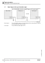
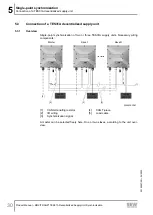
For the synchronization of the units, it is necessary to connect the synchronization sig-
nals. The following figure shows the installation diagram for the synchronization.
TES31-Master
X5122
X5121
TES31-Slave 1
X5122
X5121
TES31-Slave N
X5122
X5121
...
30902995723
Block diagram
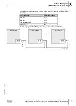
The synchronization signal is connected using the CAN bus cable. Make sure that the
bus is terminated with 120 Ohm resistors.
Cable length
The permitted total cable length is 100 m.
29190657/EN – 04/2020


